
Define the part and its scope
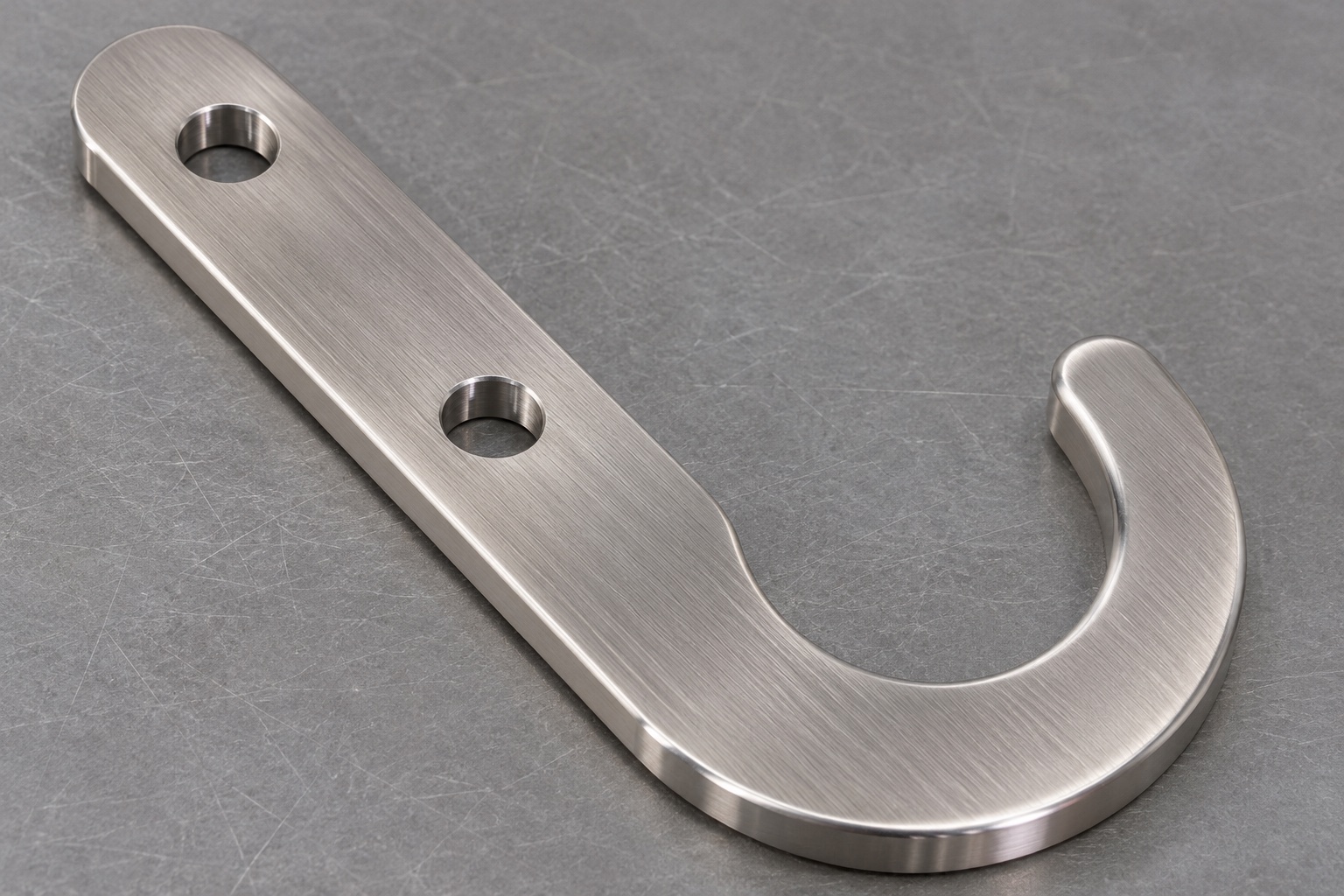
A hook plate in an equipment cabinet provides a mechanical interface to an approved mating carrier. The example here is a flat 316L plate with two mounting holes and an open curved hook. It is not an approved spare part or a design for hanging any specific instrument. The design owner must identify the supported article, permissible contact, load cases and cabinet constraints. A machining review can determine how to produce and inspect the drawing features. It cannot establish drying efficacy, storage duration, resistance to cleaning agents or safe working load from a material designation and an image alone.

Read the mating section before quoting
Ask for a section through the rail or mounting block and the carrier that enters the hook. The plate face, fastener clearances and mating outline all affect whether the carrier reaches the intended seat. Note any nearby surfaces that limit insertion or removal. Keep an approved solid model or section linked to the drawing revision rather than deriving clearance from the nominal hook radius. A flat plate with accurate mounting holes may still interfere with adjacent hardware. Review the relationship at the final installed orientation, but perform preliminary geometry checks with inert references, not with clinical instruments.
Assign the mounting datums by function
The surface that sits against the cabinet rail may define a primary plane. The locating feature can be a hole, an edge or a separate interface; two clearance holes are not automatically a precise locating system. Confirm the datum scheme before selecting fixture pins. A check with two snug pins may overconstrain a part intended to float during assembly. Conversely, unrestricted hole clearance can hide a profile shift that matters after the plate is positioned. State which face and feature establish the measurement origin, and reproduce the defined restraint rather than pressing a bowed blank flat without recording it.
Separate throat clearance from seating profile
The hook mouth controls access; the inner curved region controls where the mating carrier can seat. A single nominal diameter does not describe the entire opening. Specify the relevant sections, entry clearance, tip contour and minimum remaining material per the approved design. An inspection path should include the transition into the straight shank as well as the concave region. If the carrier enters at an angle, a static width check may miss interference during insertion. Report the actual contact location from a fixture or gauge check. Do not remove material from the tip to solve a clearance issue without approval.
Specify stock and finish independently
Identify the 316L material specification, product form, thickness condition and required lot traceability. Stock near the finished thickness may reduce face machining, but only if its form and surface meet the drawing. An alternative blank process can leave a different edge condition and affect available machining allowance. Describe the final surface separately from the stock designation. Where passivation or another treatment is specified, agree the sequence, process evidence and final inspection condition. Neither a bright appearance nor the alloy name proves that a particular cleaner, exposure cycle or cabinet workflow is suitable.
Plan roughing and finishing with support
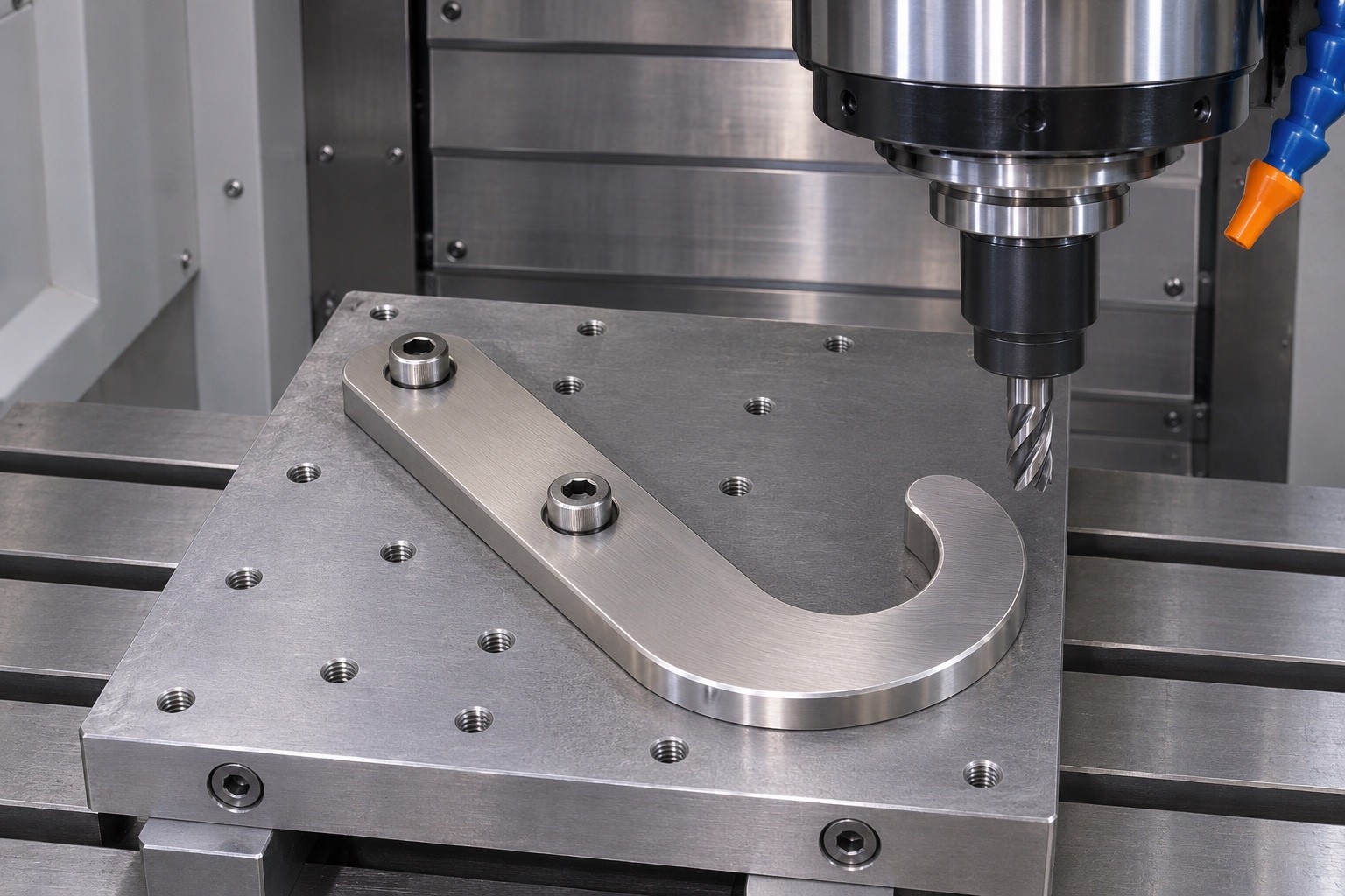
Support the broad face while maintaining access to the outside contour and open throat. A rough blank can be held on temporary material that is removed after a stable reference is established. Alternatively, approved mounting holes can support a fixture when the rest of the perimeter must be clear. A narrow hook tip may deflect if it is cut without support or if a worn tool rubs rather than cuts. Leave a consistent finish allowance and review tool access at the tightest concave segment. Check the released part after the final cut; the fixture can conceal out-of-plane movement.
Specify accessible inside radii
The cutter must reach the concave boundary without colliding with the shank, tip or fixture. A drawing that implies a sharp internal transition may require a design discussion rather than a smaller cutter by default. Tool diameter, engagement and extension affect how closely the tool follows the intended curve. Review the transition for local notches, steps or a remaining cusp. Do not substitute a general edge-break note for the profile tolerance. A controlled blend can be useful if the designer defines its extent and the preserved section. Compare the measured profile with the model in a consistent alignment.
Treat edge finishing as controlled work
Name the edges that can contact the approved carrier and those that must preserve a reference. Specify whether the requirement is a bounded chamfer, radius or absence of raised material. Deburring must reach both faces at the throat, the rounded tip and the hole exits. Aggressive polishing can change an entry dimension or leave a recess that is difficult to inspect. A visual check under suitable light can detect raised burrs, but it does not establish a radius or roughness value. Keep the inspection method and locations explicit if the drawing requires quantified finish data.
Build a feature-specific inspection plan
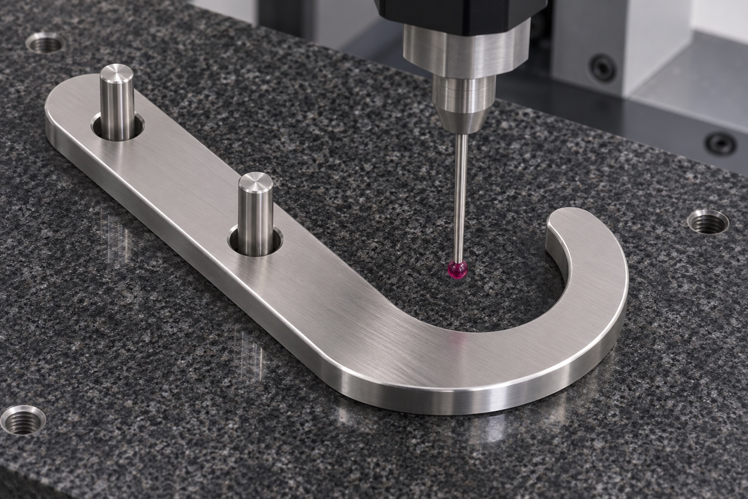
Check thickness, mounting-face form, hole pattern and hook contour as separate characteristics. Probe the concave shape where the stylus can reach without contacting a neighboring edge. An approved optical method may be useful for profiles that are difficult to access, provided the measured plane is defined. Compare readings at the correct height if a chamfer crosses the viewing plane. Record the fixture and reference alignment, not just a pass result. If finish processing is required, measure the accepted state after treatment where specified. Record uncertainty and apply the agreed decision rule near a tolerance boundary.
Use an inert fit reference
A representative carrier gauge can show whether the hook opening and seat are accessible in the defined orientation. Document the gauge revision, support and sequence; do not infer strength or operational suitability from an easy fit. If the gauge catches, identify whether the interference comes from the profile, a burr, the rail reference or an incorrect insertion path. Compare dimensional evidence before changing the part. Never treat a forced fit or hand-polished sample as proof of conformance. Any structural, retention or workflow validation belongs to the device owner and requires separate acceptance criteria.
Keep cleanliness and protection explicit
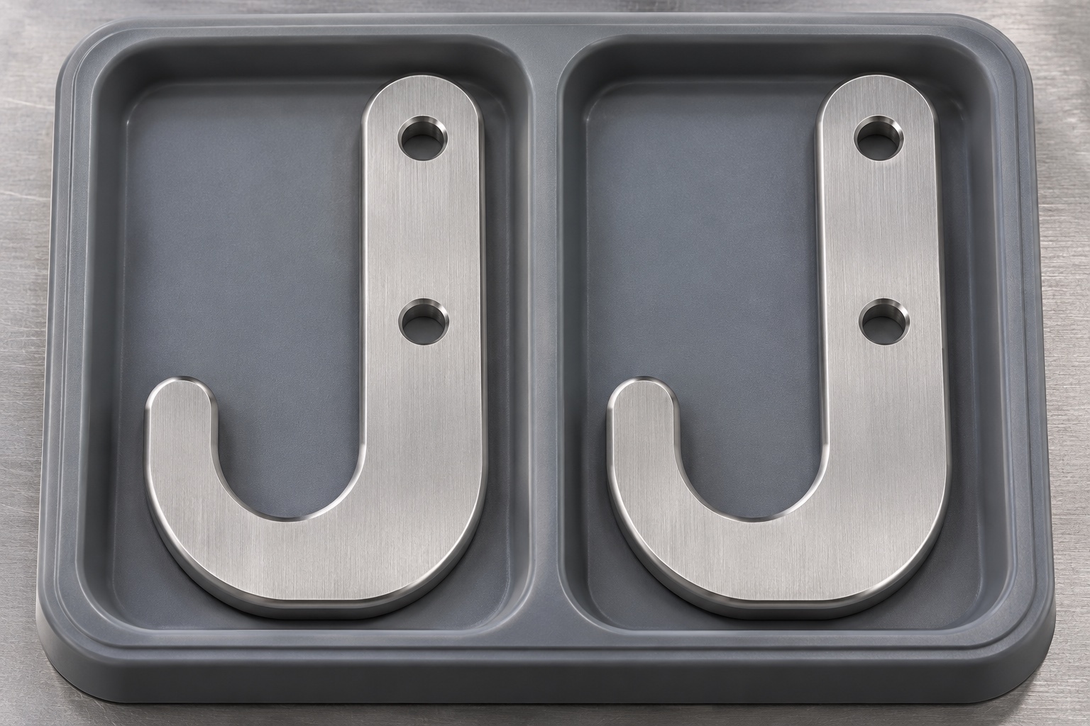
Remove machining residues according to the agreed component cleaning method. Check the inner curve, through holes and mounting face before packing, paying attention to recesses that can retain particles. Separate parts so the tips cannot strike adjacent plates or rub their finished faces. Choose protective material that does not leave residue on the contact region. Record the actual cleaning and packaging scope, along with revision and lot where required. This protective packaging does not establish sterility or a validated cleanliness class. Any additional requirements must be specified and supported by evidence rather than inferred from the cabinet application.
Ask for a release package that answers the real questions
Provide the current drawing, CAD model, mounting and carrier envelopes, material requirement, quantity and final finish. Identify the contact and clearance zones, edge limits and relevant inspection sections. Request a proposed route, datum and workholding plan, and feature-level measurement evidence. Define who owns any mechanical load, compatibility and cabinet validation. The first article should show what was measured, how it was supported and what remains outside the machining scope. Clear inputs make quotations comparable and reduce the risk of correcting a good profile to match an incorrect fixture.
FAQ
Do two mounting holes fully locate the hook?
Not necessarily. Clearance holes may only fasten the part. The drawing and assembly determine the actual locating features, datum order and accepted mounting condition.
Is throat width enough to verify fit?
No. Mouth width, inner profile, tip contour and entry direction can each influence access. Use the defined section checks and an approved inert reference where requested.
Can an accurate profile prove safe load?
No. A dimensional check does not establish strength, retention or device suitability. Those requirements need separate design review and validation by the responsible owner.
Why measure after release from the fixture?
Fixture pressure can mask bow or tip movement. Measurements in the released or explicitly mounted condition reflect the state specified for acceptance.
Does 316L guarantee chemical compatibility?
No. The exact material, treatment and exposure matter. The approved material record and dimensional report do not validate a cleaning cycle.
How should finished plates be packed?
Separate the parts, protect the curved profile and keep residues off the mating surfaces. State the actual packaging condition without claiming sterility.

tanghangyun@oemach.com