
Keep mechanical fit separate from temperature measurement
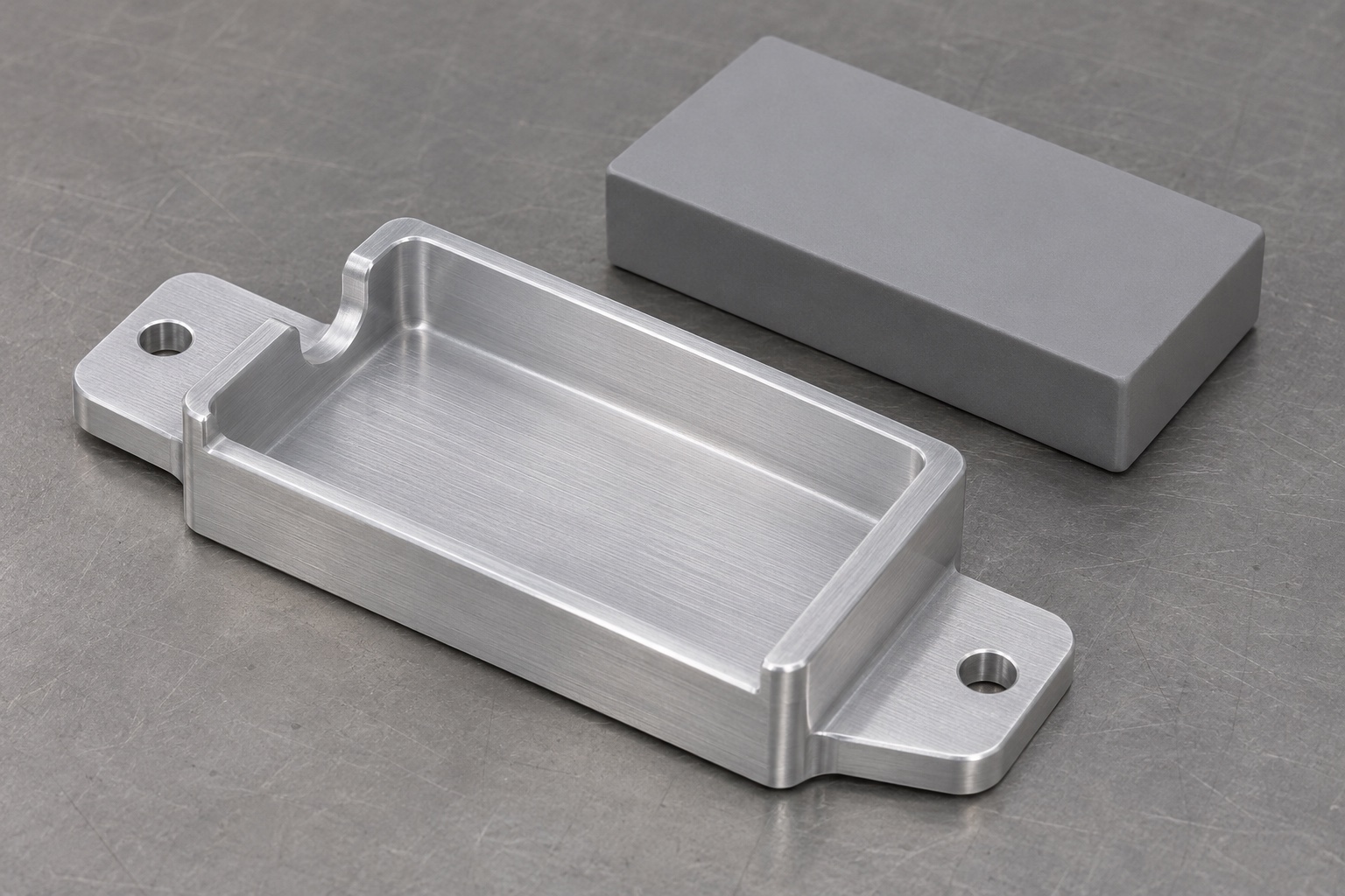
A mounting saddle can locate the body of a temperature logger on an approved exterior interface. It cannot establish probe placement, temperature accuracy, alarm response or cold-chain compliance. This guide concerns a representative CNC-milled aluminum saddle with a seating pocket, mounting ears and a cable relief. It is not an installation guide for any specific refrigerator. The device owner must authorize the mounting location and verify system performance. The machining decision is whether the component matches its drawing and approved mating envelope. Keeping those questions separate prevents a satisfactory bench fit from being mistaken for a validated temperature monitoring arrangement.

Obtain both mating envelopes
The saddle sits between the logger housing and a separate equipment mounting surface. Request the housing dimensions, corner shape, connector protrusion and approved attachment locations. On the equipment side, identify where the mounting ears can sit and whether there are obstructions behind the fasteners. A rectangular body model alone may omit the plug and the space needed to connect or remove it. Use inert models or approved envelope gauges for preliminary review. Do not assume the housing can be drilled, modified or clamped at a convenient spot. Document which interface is fixed and which permits movement or adjustment.
Make the seating and locating surfaces explicit
An exterior mounting plane and a pocket floor perform different jobs. The first relates the saddle to the equipment; the second supports the logger body. Identify which faces establish lateral location and where clearance is intentionally present. If a pad or liner is specified, include its installed geometry and attachment in the review. A broad flat floor does not guarantee that every point of the housing touches it. Differences in corner radii can suspend a body above its seat. Dimension the designated contact regions and wall locations from the functional datums, not from an exterior contour added only for appearance.
Relate hole position to the seating geometry
Two clearance holes may be adequate for fastening but may not define a repeatable location by themselves. Check how the saddle is positioned before tightening and how the mounting pattern relates to the pocket. If one hole is a slot, specify its direction, end shape and permitted travel; do not treat a slot as a round hole with a larger tolerance. Confirm clearance for the approved fastener head, washer and tool. An inspection report should distinguish hole size, pattern position and usable head clearance. A hole may meet diameter requirements while its relationship to the pocket or mounting edge remains incorrect.
Plan the pocket to suit machining access
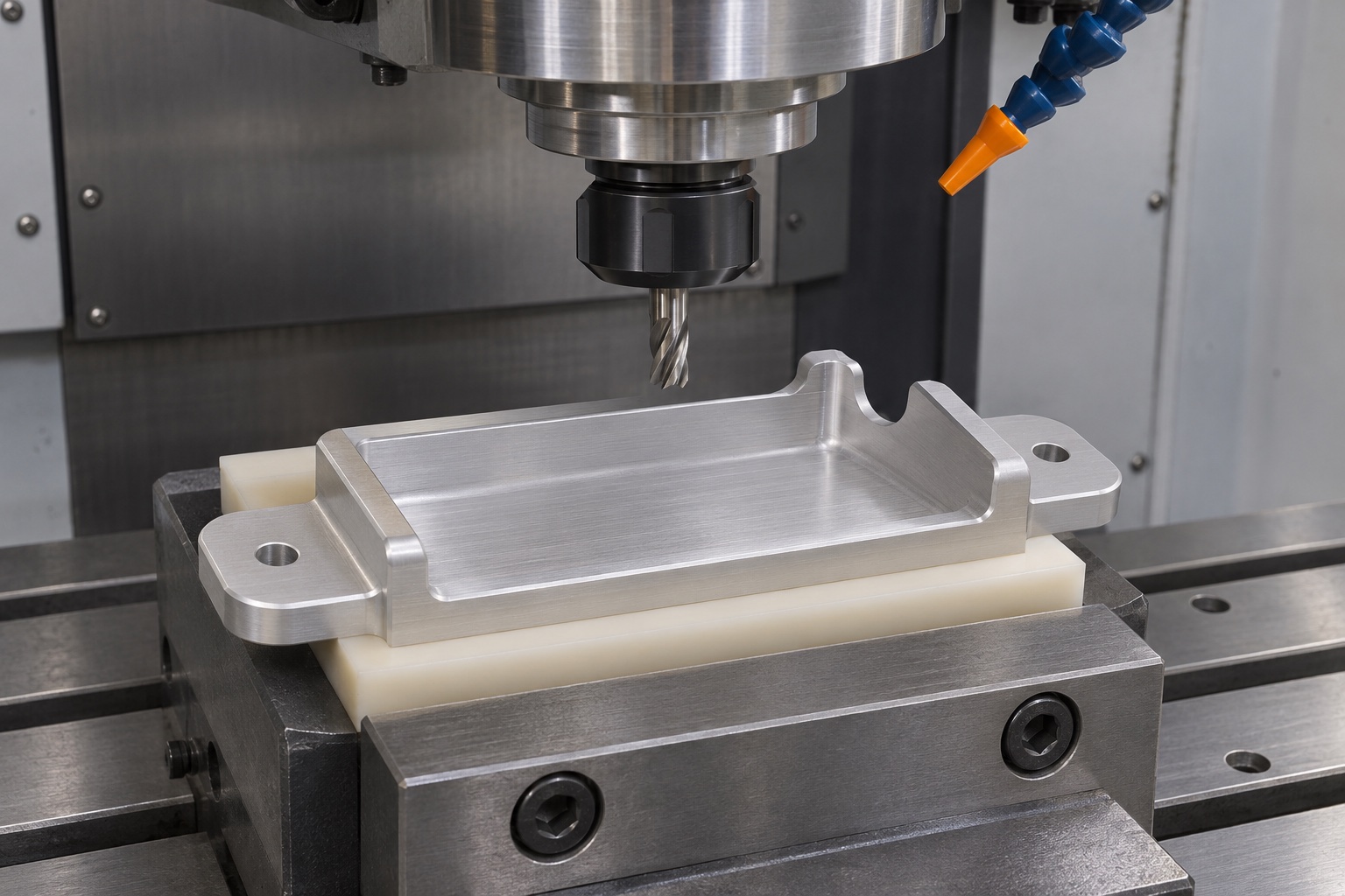
An internal radius is a consequence of rotary tool access unless a different method is agreed. Define the required corner clearance rather than assuming a sharp inside corner is necessary. A shallow pocket may be easy to rough, but its floor can move as material is removed or as a part is released. Select support that does not press thin walls inward. Plan the finish cut after the effects of roughing are understood. If the pocket includes separate contact pads, identify the surfaces that share a plane. Inspect after release and compare the result with the defined mounted condition only when requested.
Define the cable relief by its envelope
The relief provides room for an approved cable or connector envelope; it is not a substitute for strain relief. Its width, depth, position and entry radius should be described relative to the seated housing. Check the intended insertion or removal direction and possible interference with the fastener tool. A cable notch that looks generous from above may still interfere at the lower wall or corner. Avoid assuming a minimum bend radius without the cable maker's data and device owner's requirements. A bench check with a solid envelope can reveal contact, but it does not demonstrate cable service life or electrical safety.
Specify material and finish at the drawing level
Name the required 6061 stock form and condition, along with any approved finish, masking and material record. Do not assume that two aluminum stock forms machine or respond to finishing identically. If a coating is required, agree which dimensions apply before or after treatment and whether contact areas must be masked. The coating route can change usable clearance in a pocket or a hole even if the underlying machined geometry was correct. Review dissimilar metal interfaces and exposure with the equipment designer where relevant. The machining specification should not describe a finish as universally suitable for cleaners or equipment environments.
Control cable and housing contact edges
Set limits for burrs and edge breaks at the relief, wall tops, mounting holes and pocket transitions. A general instruction to remove sharp edges is insufficient if an edge also locates a body or determines clearance. Use a cleanup method that leaves the agreed contact geometry intact. Verify the relief with accessible profile measurements and a visual check for raised material. At a through-hole exit, check the underside for a burr that could hold a mounting ear off its seat. Do not substitute a cosmetic polish for a defined edge condition. Record corrections that require remeasurement of a functional feature.
Check flatness and seating in the intended condition
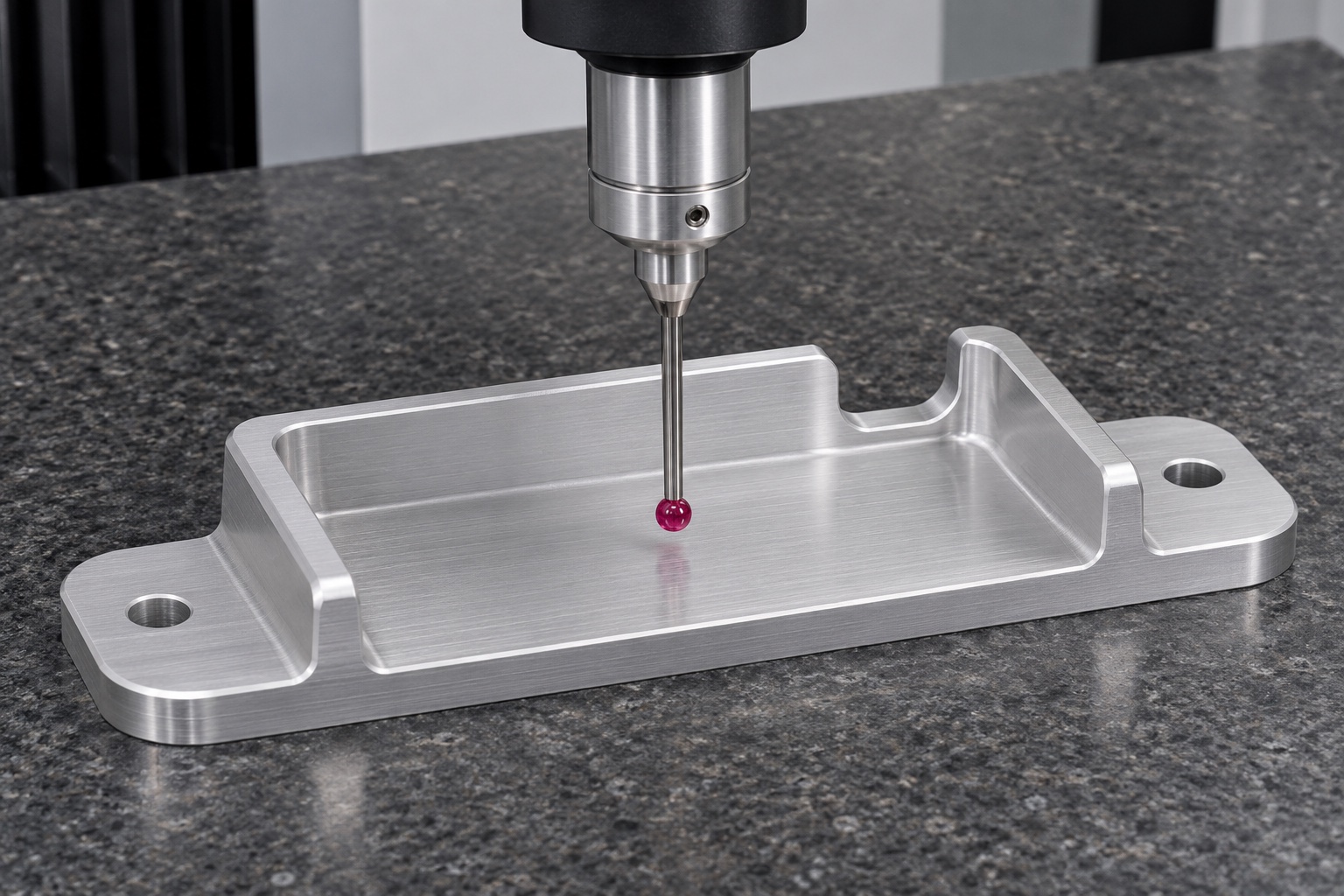
Specify whether the mounting surface is checked free on defined supports or assembled with agreed restraint. Flatness is different from parallelism between the mounting plane and the pocket floor. A fixture can pull a thin saddle flat without proving its free-state geometry. The inspection plan should cover the pads, pocket profile, hole locations and cable relief independently. Document the probe access, datum setup and condition after finishing. An inert body gauge can reveal seating contact and removal clearance, but it does not measure every drawing feature. Keep dimensional results and bench observations separate so that their limitations are visible.
Evaluate fit without altering the refrigerator
Use an approved interface plate or controlled model for the bench review. Confirm housing insertion, seating, accessible fasteners and removal space in the agreed sequence. The review should not require modifying refrigeration hardware, opening a sealed panel or rerouting a live sensor. Record what touches and where, including any conflict found at a connector envelope. If the body rocks, compare corners, pads and the reference fixture before removing material. The responsible equipment owner must review any proposed location and system effects separately. The supplier should state clearly whether the check used inert parts and which actual interface data was supplied.
Preserve the as-inspected geometry in packaging
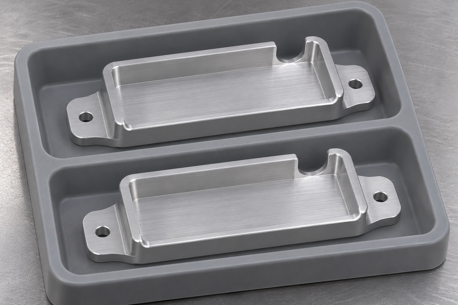
Use separated pockets or approved separators that do not bear on the cable relief or thin wall edges. Protect mounting pads and the floor from abrasion. Inspect the part for chips or residue after the agreed cleaning step and before packing. If a finish is susceptible to marking, confirm that the separator material and handling sequence are approved. Maintain identification of drawing revision and material lot when required. Protective packaging does not imply sterilization or controlled cold-chain shipping for the component. If additional transport or cleanliness qualification is needed, define the criteria separately rather than adding a general medical-grade claim to the package.
Define the release evidence before requesting a quote
Provide the drawing and model revisions, housing and connector envelopes, mounting interface, material and finish, quantity and requested evidence. Specify which features control fit and how they will be evaluated. Ask for a proposed operation order and the condition at final inspection. A useful supplier response flags inaccessible radii, coating allowances and fixture-dependent measurements before samples are made. Assign refrigerator installation and temperature validation to the responsible design authority. This keeps the quotation focused on geometry, manufacturing and delivery, while making clear where further system evidence is needed. The same evidence boundary should appear in the first-article report.
FAQ
Can the mount establish temperature accuracy?
No. The mount locates an enclosure mechanically. Probe placement, calibration and system behavior require separate evaluation by the equipment owner.
Why request the connector envelope?
The plug and cable can extend beyond the logger body and interfere with a wall, fastener or tool. The approved envelope makes those checks reproducible.
Does a flat pocket floor guarantee seating?
No. Housing corners or a raised edge can prevent contact. Inspect the relevant surfaces and compare the actual mating envelope without forcing the body into position.
When should the pocket be measured?
Use the drawing-defined condition, including any required finish and restraint. Measurements under cutting clamps are not a substitute for the agreed final condition.
Is a cable notch a strain relief?
No. A notch may provide clearance. Any retention, bend or electrical requirement needs a separate design and verification.
Can the saddle be fitted to any refrigerator?
No. Mounting location and attachment are equipment-specific. Use only approved interface data and keep a bench review distinct from authorized installation.

tanghangyun@oemach.com