
This article relates the mounting geometry to the encoder signal, emphasizing that specific clearances and tolerances must come from the selected product installation manual and cannot be applied across models.
Qualified mounting surface is only a prerequisite; scale locking, readhead attitude, temperature constraints and full-stroke signal quality jointly determine whether the feedback system can work stably. The specific process still needs to be combined with the tape or scale reference, mounting surface flatness, read head clearance, parallelism, thermal expansion, tightening sequence and signal quality confirmation.
Typical problems, causes, controls and evidence
| Problem | Likely cause | Control action | Acceptance evidence |
|---|---|---|---|
| Local signal amplitude decreases | Readhead clearance or yaw/pitch exceeds the corresponding product installation window | Set the gap and attitude strictly according to the encoder manual | Full travel signal quality and installation geometry recording |
| The ruler bends after locking | Uneven mounting surface, improper tightening sequence, or thermal expansion constraints | Correct the mounting surface and perform progressive locking according to the manual | Free state, post-locking flatness and temperature recording |
| Position deviation occurs after repeated installation | The positioning reference and readhead reset methods are inconsistent | Set reproducible benchmarks and fix setup gages and procedures | Comparison data of zero position and full stroke before and after disassembly and assembly |
First determine the installation window according to the specific encoder
Open linear encoders usually consist of a scale and scan head, and different models have different mounting clearances, pitch, yaw and roll tolerances. Technicians should obtain the complete model number and the latest version of the installation manual, and then review the flatness, side shoulders and adjustment range of the mounting base. When there is no parts manual, general millimeters should not be given or parameters of other brands should be directly applied.
Mounting surface shape changes readhead clearance
Even if the height of the long-travel mounting surface is appropriate at both ends, warping in the middle will still cause the readhead clearance to change. The entire surface needs to be evaluated at specified supports and temperatures, not just a few endpoints. Datum shoulders, screw countersinks, and seams can also cause localized bending of the ruler. Roughing and finishing should be separated, materials should be removed evenly and retested after loosening the clamp.
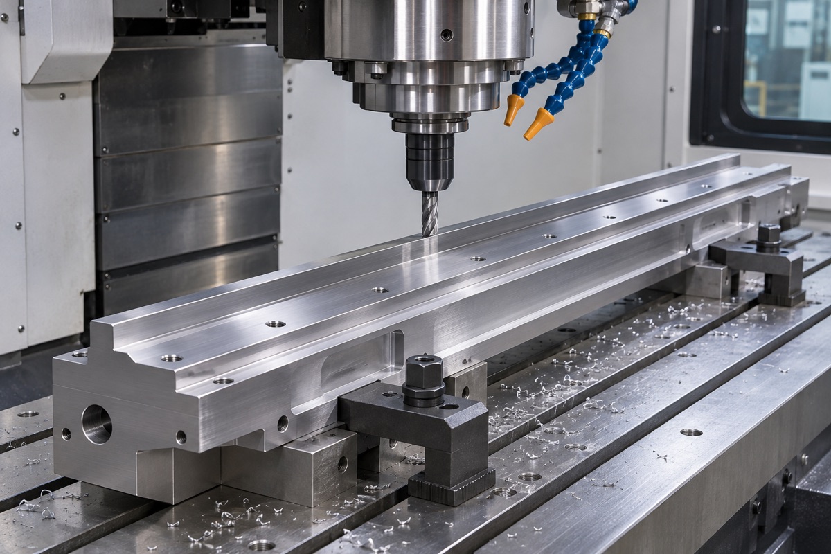
Long mounting surfaces require controlling the overall shape and retesting after loosening the clamp.
The thermal expansion of the ruler must match the constraint method
The coefficients of thermal expansion of the scale, mount, and body materials may differ. Fixed points, elastic installation or bonding methods should comply with the manufacturer's design, and cannot be forced to be flat by adding fastening points. Relative displacements under temperature changes translate into position errors or local stresses. Assembly records should include ambient temperature, installation sequence, and curing conditions.
The read head bracket must have stiffness and adjustability
The readhead bracket must maintain clearance and posture while allowing for initial setup and adjustment. If it is too thin, it will be deformed by the cable force or locking force, and if it is too constrained, it will be difficult to adjust to the manual window. During processing, control the relationship between the mounting surface, hole system and reference edge; during assembly, use manufacturer's gauges or specified tools to fix the locking direction and review the full stroke.

The specific gap and attitude must be set according to the corresponding encoder manual.
Surface preparation is as important as cleanliness
Anodizing, coating or residual burrs will change the installation height and contact status; oil stains and chips can also cause the scale to partially warp. The functional surface should be masked and re-inspected after treatment, and should be cleaned according to the encoder requirements before assembly. Magnetic or reflective products may also have different restrictions on materials, contamination, and optical surfaces that must be followed by the manual.
Ultimately it depends on the signal and location results
HEIDENHAIN information clearly states that installation tolerances should be observed to obtain the specified signal quality. After assembly is completed, the signals, reference points and repeat positioning should be checked along the entire stroke and correspond to the mechanical geometric data. If the local signal decreases, gaps, postures, contamination, and ruler deformation need to be checked, rather than just adjusting the electronic threshold to cover up mechanical problems.
Summary
Qualified mounting surface is only a prerequisite; scale locking, readhead attitude, temperature constraints and full-stroke signal quality jointly determine whether the feedback system can work stably. The specific process still needs to be combined with the tape or scale reference, mounting surface flatness, read head clearance, parallelism, thermal expansion, tightening sequence and signal quality confirmation.
FAQ
Is there a uniform value for the read head gap?
No. The installation manual and gauges for the selected encoder model must be used.
Can I use screws to press the ruler flat?
Not recommended. Stress and local bending may be introduced and should be installed according to the manufacturer's fixing method.
Is it over after the three-dimensional coordinate measurement of the installation surface?
It is also necessary to check the full-travel signal quality, reference position and repeatability after assembly.
Ready to get a quote for your CNC machined parts?
Submit your engineering drawings to qiancj@oemach.com. We support prototype sampling and small-batch production with strict tolerance control.