
This article starts from the repeatability of measurement results and explains why the base, column, motion axis and optical interface must be designed and accepted as a structural system.
The qualified flatness of a single structural part does not mean that the whole machine is stable; assembly stiffness, motion reference, temperature, vibration and locking status must be verified. The specific process still needs to be confirmed by combining the measurement axis, the relationship between the column and the workbench, structural stiffness, vibration isolation, temperature conditions, motion benchmarks and retest procedures.
Typical problems, causes, controls and evidence
| Problem | Likely cause | Control action | Acceptance evidence |
|---|---|---|---|
| Contour scan repeatability is poor | Insufficient base/column stiffness, rail attitude, or environmental vibration | Unify structural benchmarks and verify assembly stiffness and vibration isolation conditions | Structural geometry, vibration conditions and repeat scan data |
| The microscope field of view is out of focus after moving | The relationship between the table plane, column verticality and optical axis is inconsistent | Controlling motion surfaces and optical interfaces in a common coordinate system | Focal plane changes and position reproduction records throughout the entire stroke |
| A single piece is qualified but the whole machine drifts | Locking, temperature gradients or cable forces change assembly configuration | Thermal stabilization according to the complete machine status and re-measurement of key geometries | Temperature, locking conditions and drift curves |
Structural components serve the measurement chain rather than appearance
A profilometer relies on the movement of a probe or optical sensor along a datum, and a measuring microscope relies on an objective, a worktable, and a ruler to establish coordinates. Small deformations in the base, columns and mounting brackets enter directly into the measuring chain. The drawing review should infer the structural characteristics from the error path between the measured object, the sensor, the motion axis and the sample support, rather than just judging the stability based on "thick plate, large base".
Common datum connects base, column and workbench
Base planes, column mounting surfaces, rail shoulders, and optical head interfaces should be referenced to a common traceable datum. If each part is best-fitted separately, the axes may not be orthogonal or the focal plane may change with stroke after assembly. Key interfaces should be finely machined in stable clamping. The assembly positioning surface should avoid false contact caused by chamfers, coatings or burrs, and the tightening sequence should be specified.
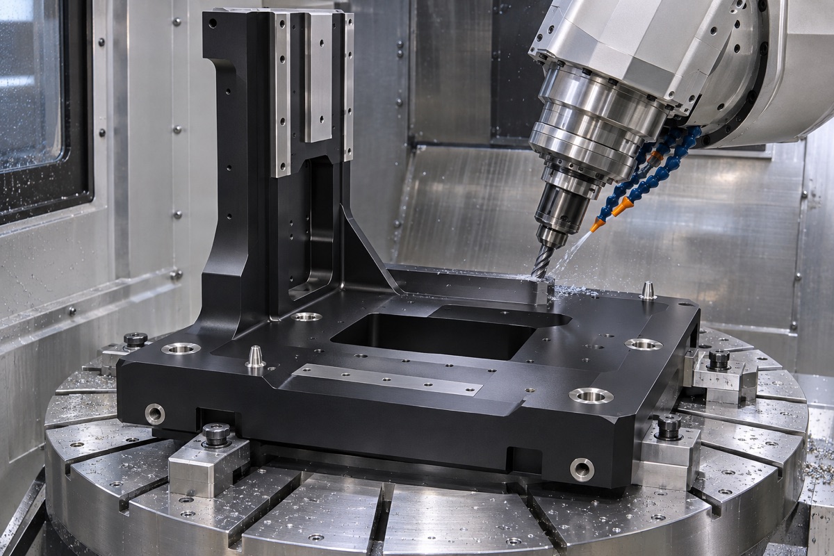
Bases, columns and interfaces need to be machined around a common measuring coordinate system.
Stiffness and vibration are evaluated by direction
A high-quality measurement structure must not only withstand static loads, but also suppress responses caused by external vibrations and motion acceleration and deceleration. Structural stiffness can vary greatly in the vertical and horizontal directions, and table extensions, column heights, and cable pulls can also change local modes. Taylor Hobson's vibration isolation equipment description emphasizes stable, rigid support; the isolation or structural solution should be selected based on the site vibration spectrum for a specific project.
Thermal stability determines long-term drift
Thermal expansion of materials, heat source location, and environmental gradients can alter optical axis height, guide straightness, and scale readings. Thermal stability must be achieved before finishing and inspection, and the temperature must be recorded in the report; the warm-up time and long-term drift must also be observed after installation. Measuring equipment catalogs such as Mitutoyo often give performance under specified temperature conditions, which shows that the measurement conditions are an integral part of the specifications.
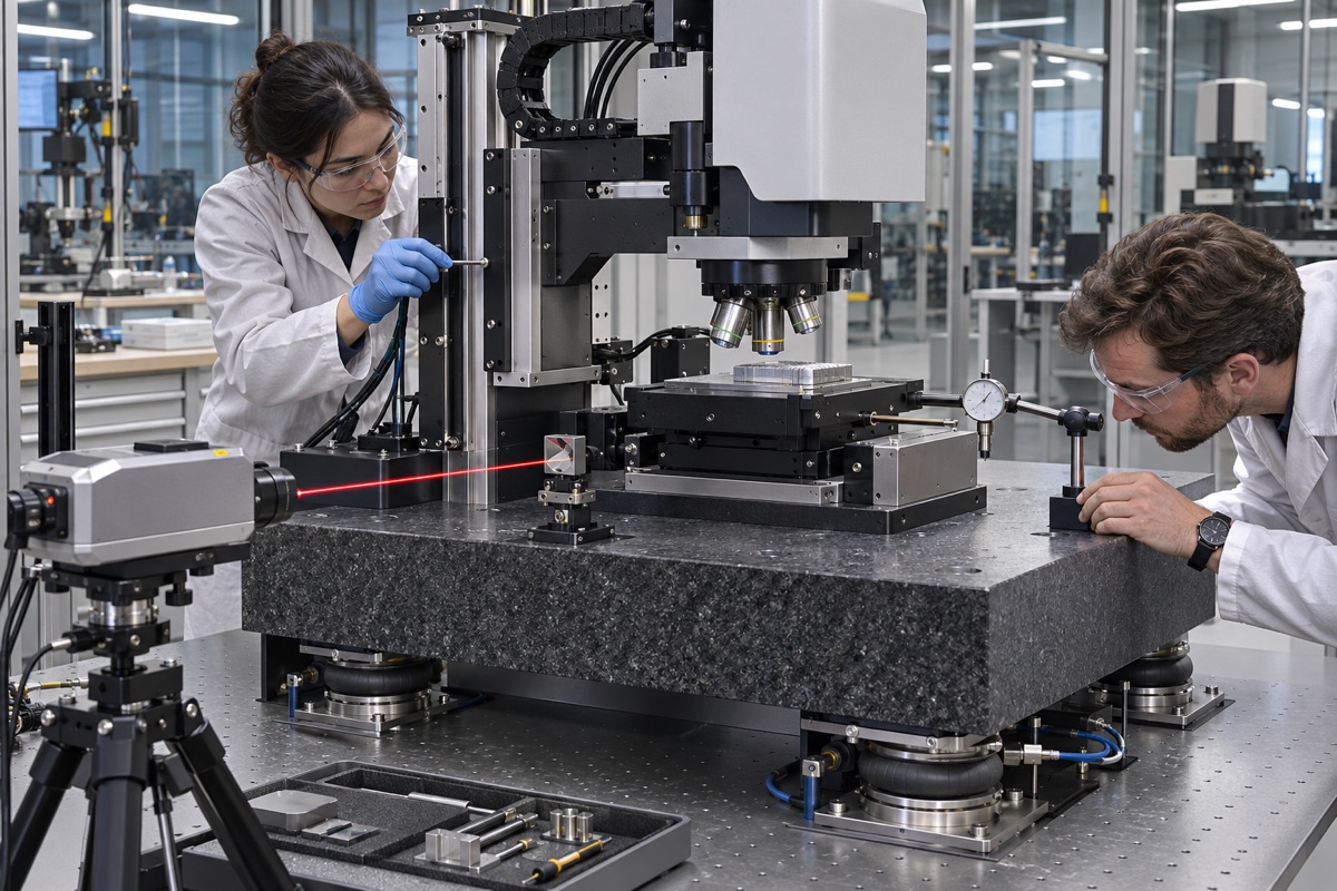
Post-assembly axis, vibration and repeatability require system-level verification.
Surface treatment must not damage the functional interface
Aluminum structural parts are often anodized or coated, and cast iron and steel parts may be painted or rust-proofed. Treatment layer thickness, masking edges, and spray buildup can change the mounting surface and ground/thermal paths. Functional interfaces should clearly address front and rear dimensions, masking and re-inspection requirements. The large removal structure should also be stabilized after rough machining and arranged for free state retesting.
Complete machine verification of connection geometry and repeatability
Part acceptance can check plane, vertical, linear and hole system positions, and after assembly, table movement, focal plane changes, probe trajectories and repeated measurements must be verified. Optical profiler data such as ZYGO also emphasize the impact of vibration on measurement quality. Final qualification should be based on the approved calibration and repeatability results of the entire machine, rather than applying the nominal parameters of a commercial instrument.
Summary
The qualified flatness of a single structural part does not mean that the whole machine is stable; assembly stiffness, motion reference, temperature, vibration and locking status must be verified. The specific process still needs to be confirmed by combining the measurement axis, the relationship between the column and the workbench, structural stiffness, vibration isolation, temperature conditions, motion benchmarks and retest procedures.
FAQ
The heavier the base, the more stable the measurement will be.
Not necessarily. Mass, stiffness, modes, isolation, support and thermal gradients all determine stability.
Can all structural parts be reported and accepted as single pieces?
Single-piece reporting is necessary but not sufficient, and post-assembly verification of shafting relationships and measurement repeatability is required.
Can aluminum alloy be used as high-precision structural parts?
Yes, but material condition, residual stress, thermal expansion, connections and surface treatment need to be controlled.
Ready to get a quote for your CNC machined parts?
Submit your engineering drawings to qiancj@oemach.com. We support prototype sampling and small-batch production with strict tolerance control.