
This article discusses rotation readings, actual angles, locking and maintenance, and optical component stress separately, and provides a complete control path from hole system processing, rotation pair matching to assembly adjustment and retesting.
The high-resolution scale only represents readability; the true accuracy must be proven by the center of rotation, back-and-forth differential, locking front and rear drift, and system retest after the optics are installed. The specific process still needs to be combined with the stress boundary of the optical component, the center of rotation, angle readings, drift before and after locking, repeated loading and unloading, and confirmation of ambient temperature.
Typical problems, causes, controls and evidence
| Problem | Likely cause | Control action | Acceptance evidence |
|---|---|---|---|
| Angle rebound after locking | The locking force changes the contact of the rotating pair or the elastic deformation of the bracket | Separate the adjustment and locking force paths, fix the locking torque and sequence | Locking front and rear angle, repeated locking and back-and-forth adjustment records |
| Optical performance changes after the wave plate is installed | The pressure ring is uneven, the contact edge is too narrow, or the bonding shrinkage introduces stress. | Limit the clamping force, optimize the contact strip and test-fit with equivalent parts | Mechanical posture and polarization/optical re-measurement records |
| The zero position does not repeat after disassembly and assembly | Positioning surface contamination, chamfer interference or adjustment mechanism backlash | Define three-point/stop positioning and cleaning, alignment and locking procedures | Angle and optical axis data after multiple disassembly and assembly |
First define what “angle accuracy” specifically refers to.
A mount may be labeled with scale resolution, vernier readout, adjustment sensitivity, and repeatable positioning at the same time, but these concepts are not interchangeable. The project should first clarify whether it is manual reading, encoder feedback, or the actual optical axis angle after locking; it should also specify the forward and reverse direction, measurement temperature, and effective angle range. If you only make the scale lines denser without controlling the rotational pair and locking deformation, the readings will appear fine and the results will be unstable.
The center of rotation comes from the hole system and the end datum.
The effective optical center of the wave plate or crystal should be as close as possible to the mechanical axis of rotation. The bearing position, stopper, rotating ring end face and base mounting surface must be processed around a common datum to avoid dismantling the axis by turning over multiple times. The key holes should be finished with the mounting clamp; when it is necessary to change the mounting, the processed functional benchmark should be used and repeated positioning should be verified. The surface treatment thickness also enters the rotating secondary dimension chain.
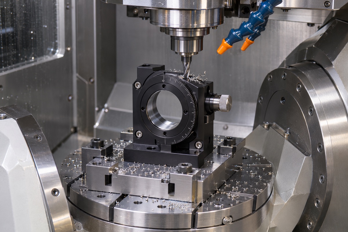
Key holes, notches and end faces are machined around a common rotating datum.
The clearance of the rotating pair should take into account the feel and hysteresis
If the gap is too large, it will easily produce radial movement and angular backlash, and if it is too tight, it will increase friction, crawling and local wear. The selection of bushings, bearings or precision fits must be combined with the adjustment method and load, and cannot just pursue zero clearance. Fine-tuning threads, worms or tangential drives also requires checking the center of rotation, preload and reciprocating direction. Actual performance should be judged by full-stroke testing rather than single-point feel.
The locking mechanism cannot change the adjustment result
If the locking screw directly pushes the rotating ring, it will change the contact state and produce angular rebound. A more stable design is to make the locking force symmetrical, repeatable, and as decoupled from the adjustment direction as possible. The processing end should control the locking contact surface, thread axis and local wall thickness, and the assembly end should fix the locking torque and sequence. The acceptance check should record the angle difference before and after locking and the distribution of repeated locking.
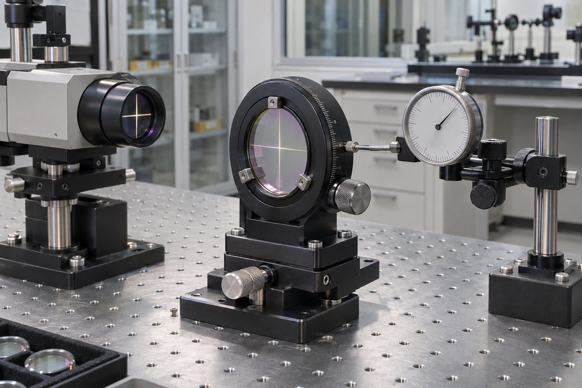
Angle repeatability needs to be compared with back-and-forth adjustment, before and after locking, and repeated loading and unloading.
Optical parts should be clamped to avoid stress and slippage
Wave plates and crystals can be sensitive to clamping stress, temperature, and edge loading. Seams, pressure rings or flexible holds should ensure uniform contact and leave space for cleaning, loading and unloading, and thermal expansion. Poor positioning cannot be compensated for by vigorous compression. Equivalent parts can be used to first verify the clamping force and slippage, and then optical testing can be performed to confirm that the polarization or wavefront behavior after installation has not been damaged by mechanical stress.
Finally, two sets of evidence, mechanical and optical, were used to close the loop.
Mechanical inspection can cover the rotation axis, end face runout, radial play and locking displacement, while optical inspection confirms the actual angle and optical path performance. Public articles should not give universal arcsecond or Newton-meter indicators across structures; specific limits should be determined by the optical system error budget, mounting structure and use environment, and verified under an approved measurement plan.
Summary
The high-resolution scale only represents readability; the true accuracy must be proven by the center of rotation, back-and-forth differential, locking front and rear drift, and system retest after the optics are installed. The specific process still needs to be combined with the stress boundary of the optical component, the center of rotation, angle readings, drift before and after locking, repeated loading and unloading, and confirmation of ambient temperature.
FAQ
Is scale resolution equal to rotation accuracy?
No. The scale is the reading ability, and the accuracy is also affected by hysteresis, eccentricity, locking drift and measurement method.
Is the tighter the lock more stable?
No. Excessive locking force may deform the bracket or crush the optical components. Operation should be carried out according to the verified torque and structure.
Can the installation frame be accepted using only three coordinates?
Three-dimensional coordinates can verify mechanical geometry, but the actual optical axis angle and the force on optical parts require optical re-measurement.
Ready to get a quote for your CNC machined parts?
Submit your engineering drawings to qiancj@oemach.com. We support prototype sampling and small-batch production with strict tolerance control.