
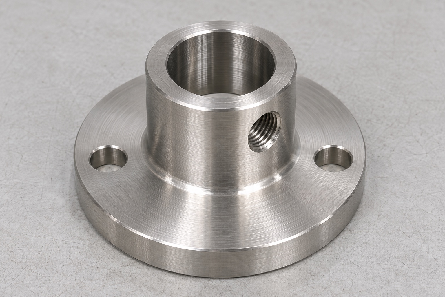
Start with the nozzle holder's mechanical interfaces
A dental mill coolant nozzle holder can appear simple while combining several different locating functions. The representative geometry discussed here is a short cylindrical boss on a round flange, with a smooth axial bore, a radial locking thread and two flange mounting holes. Precision CNC machining must relate these features to the intended installation references. This guide addresses the holder as a mechanical equipment component, not a finished dental device. It does not establish coolant delivery performance, pressure capability, clinical suitability or compatibility with a particular milling machine. Those questions require separate design evidence.

Translate assembly intent into drawing requirements
Before requesting custom stainless steel parts, identify which surface supports the holder and which feature positions the nozzle. A flange underside may be the mounting reference, while the axial bore locates a mating cylindrical feature. The radial thread may retain that feature without determining its final axis. These roles should be explicit rather than inferred from a rendered model. Ask the designer to distinguish seating faces, clearance surfaces and functional edges. Include the mating envelope where available, but do not convert an unspecified assembly preference into an invented machining tolerance during quotation.
Specify the actual 316L supply condition
The designation 316L is only the beginning of a material requirement. A procurement package should identify the applicable material specification, required supply condition, traceability expectation and any restrictions relevant to later processing. Bar stock, a near-net blank and another approved starting form may lead to different machining plans. A supplier should not assume that a common grade name proves suitability for an unknown coolant or cleaning chemistry. Material identity, process residues and operating exposure are separate matters. Review them with the equipment owner before approving substitutions or claiming corrosion performance.
Use turning to establish the axial relationship
For this round component, CNC turning is a practical way to create the boss, flange diameter, axial bore and seating face from coordinated references. The sequence should preserve sufficient support around the bore and avoid excessive projection from the workholding. Whether the bore is drilled, bored or finished by another method depends on its specified geometry and accessible tooling. A smooth appearance does not confirm straightness or size. Record how the finished axial features will be measured, and decide when the part can be released from its initial setup without losing the required relationship.
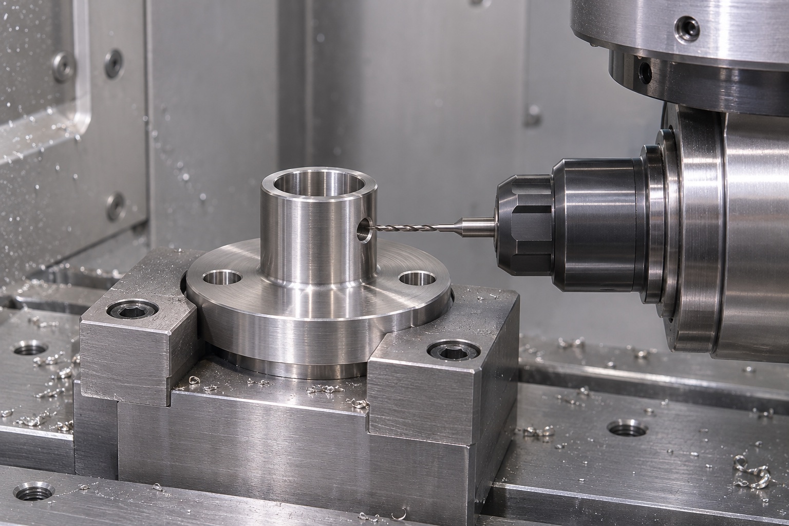
Control orientation when adding milled features
The two flange mounting holes and radial locking hole introduce angular and positional relationships that turning alone may not establish. A mill-turn arrangement or a documented secondary fixture can connect these features to the mounting face and bore. The useful question is not whether the machine has more axes, but whether the setup gives access and repeatable reference transfer. Clarify the angular orientation of the radial hole relative to the flange holes. If the drawing leaves that orientation free, preserve that freedom rather than adding unnecessary inspection and machining cost.
Plan the radial thread and its bore intersection
A radial locking thread that breaks into the axial bore creates an interrupted internal boundary. Tool travel, breakthrough location and remaining wall section deserve attention before cutting. The thread specification should state the required form and usable engagement; the bore-side edge requirement should prevent a protruding burr from interfering with the mating feature. Threading strategy depends on access and the approved design. Do not infer retention force from thread presence alone. A completed thread check and a clean intersection are distinct acceptance items, and neither replaces an assembly-level retention evaluation.
Treat cross-bore deburring as a defined operation
Cross-bore deburring for a dental mill nozzle holder should have a clear access route and a defined edge condition. An operator may need magnification, an appropriate finishing tool and a method to remove detached particles without damaging the bore. Avoid broad instructions such as polish all surfaces when only selected intersections need attention. Excessive edge removal can change the useful locating surface or thread entry. The process plan should identify where an edge break is permitted, where material must remain and how the finished intersection will be examined before the part moves to cleaning.
Keep seating finish separate from appearance
The mounting face, bore and visible exterior do not necessarily need the same surface condition. Specify functional texture where it affects seating or mating, and keep cosmetic preferences distinguishable from measurable acceptance criteria. A brighter surface can still contain a raised defect at a mounting hole. Conversely, ordinary machining marks may be acceptable on a nonfunctional exterior if the drawing permits them. If passivation or another secondary treatment is requested, define the applicable process and inspection responsibility in the purchase requirements. Do not imply that an unspecified treatment automatically validates the finished component for medical service.
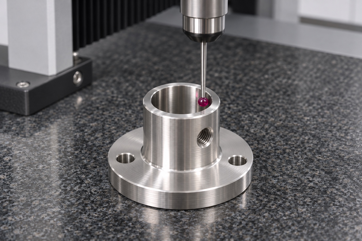
Build inspection around the reference structure
An inspection plan should connect each result to the feature that matters in assembly. Possible checks include the flange seating plane, bore size, relevant boss dimensions, mounting-hole locations and the radial thread. Select equipment that can access the actual surfaces without obscuring or deforming them. A coordinate measuring machine can support geometric inspection when its setup and probe reach are suitable; it is not a universal answer for every small internal edge. Document alternative checks for the bore intersection and thread, and identify which characteristics need a recorded result rather than a simple visual confirmation.
Separate component cleanliness from sterilization
After machining and finishing, remove process residues using a method agreed for the material and downstream use. The drawing or purchase order should define cleanliness acceptance when that is important; an unqualified instruction to make it medical clean is insufficient. Inspect bore openings and intersections for remaining particles before packing. This is a component preparation task and does not establish sterility, biocompatibility or an approved cleaning process for a complete dental system. Any such claims require their own scope, validation and responsible organization, rather than being attached to the machining quotation by implication.
Protect the bore and mounting face in transit
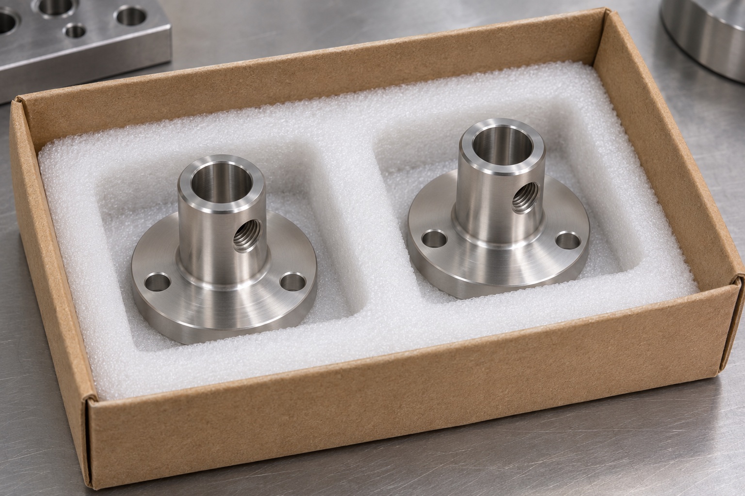
Protective packing should prevent loose parts from striking the flange seating face or entering the axial bore. Separate pockets, compatible protective material and a controlled handling sequence can help maintain the accepted condition. Keep identification associated with the lot without placing an adhesive label across a functional face. Where the customer specifies individual wrapping or a particular packaging material, confirm that requirement before production. Packaging photographs are useful for reviewing arrangement, but do not prove a cleanliness classification. The delivered packing record should describe what was actually used and any handling restrictions agreed with the buyer.
Make the RFQ complete enough to compare
A useful RFQ for precision CNC turning of 316L nozzle holders includes the controlled drawing, model revision, material requirement, quantity range, mating information and inspection deliverables. Ask the supplier to identify assumptions about bore finishing, radial threading, cross-bore access and secondary treatments. Compare quotations against the same acceptance scope instead of using a headline tolerance as the only selection criterion. Prototype quantities can be used to evaluate accessibility and assembly fit before a recurring order, provided their purpose is explicit. Approved changes should update the controlled requirements rather than remain only in an email conversation.
FAQ
Can 316L alone establish coolant compatibility?
No. Grade identity does not establish behavior in a particular coolant or cleaning process. Review the specified material condition, actual exposure and required evidence with the equipment designer before making compatibility claims.
Does a radial thread prove nozzle retention force?
No. Thread form and usable engagement are component characteristics. Retention depends on the approved assembly design and operating conditions, which require their own evaluation rather than inference from a machining inspection.
Why inspect the cross-bore intersection separately?
A thread can pass its specified check while a burr remains at the bore opening. Separate examination helps address the internal edge and particle condition without confusing them with thread acceptance.
Is five-axis machining necessary for this holder?
Not necessarily. Turning with suitable live tooling or a controlled secondary setup may provide access. Choose the process from geometry, reference transfer, quantities and inspection needs rather than an equipment label alone.
Should all surfaces receive the same finish?
Only if the approved requirements call for it. The seating face, locating bore and exterior can have different functions. Distinguishing functional texture from cosmetic preference makes quotation and acceptance clearer.
What should accompany a first-article submission?
Provide the agreed dimensional results, material traceability and relevant process records against the correct drawing revision. State any unverified assembly or cleanliness requirements explicitly so that component inspection is not mistaken for device validation.

tanghangyun@oemach.com