
CFRP and GFRP are families, not single materials. Fiber form, volume fraction, resin, layup and cure state change cutting forces, heat, abrasion and damage mechanisms.
A qualified process uses representative laminate data, proven tooling and support, controlled extraction, and acceptance evidence for entry, exit and wall condition rather than diameter alone.
Composite machining risks and controls
| Risk | Control | Evidence |
|---|---|---|
| Exit delamination | Use fitted backing and validated tool/strategy | Entry and exit micrographs |
| Wall burns while diameter passes | Control heat, extraction and sharpness | Wall and resin-damage inspection |
| Same settings fail on another layup | Qualify by material batch and layup | Material record and trial report |
Identify the complete laminate
Request the material specification, resin system, layup, thickness and critical surfaces. The abbreviation alone cannot reproduce tool life or edge quality. Batch or cure changes should trigger a review against the qualified process window.
Match tool material and geometry
Abrasive fibers wear edges and increase thrust and heat. Carbide, diamond coating or PCD may be appropriate in different cases, but point geometry, helix and cutting direction still govern peel-up, push-out and fuzzing. Validate on representative stock.
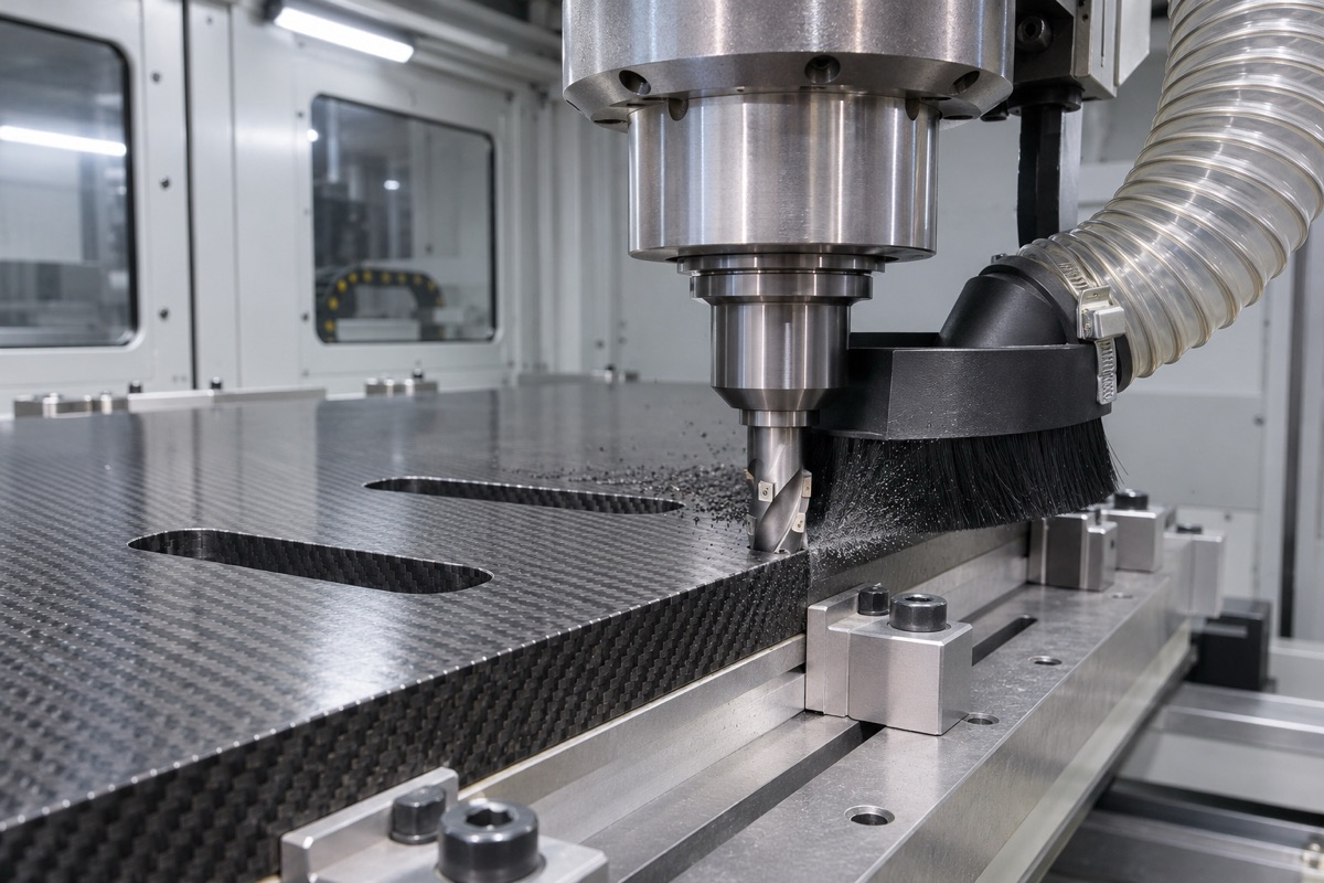
Sharp tools, rigid backing and compatible extraction jointly affect edge quality.
Support the exit and manage dust safely
As a drill approaches the exit, weakened interlaminar support increases delamination risk. Clean, close-fitting backing and a validated sequence help. Use enclosed local extraction and filtration compatible with the laminate, its resin safety data and the facility's occupational-health plan; do not improvise dust controls.
Define tool life from quality trends
A tool can still cut while already producing unacceptable delamination. Track hole count or cutting length together with entry, exit, wall and dimensional trends. Inspect both sides and use the approved microscopic or nondestructive method after changes in layup, thickness or supplier batch.
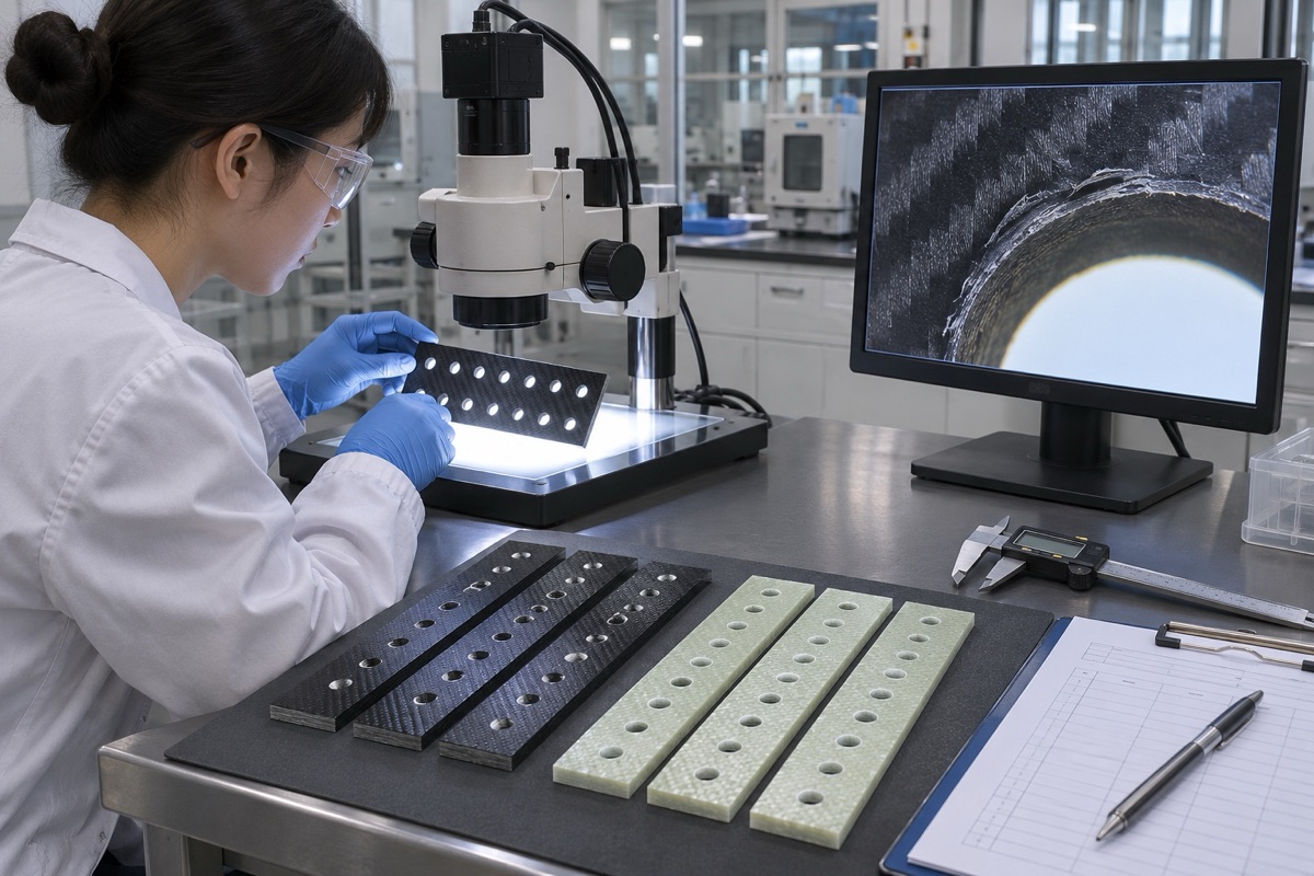
Hole diameter must be supplemented by microscopic evidence of delamination and wall damage.
Summary
Delamination control depends on complete laminate identification, matched tool geometry, rigid exit support, approved dust control and tool-life limits based on observed quality.
FAQ
Can CFRP and GFRP use one parameter set?
Not by default. Fiber, resin, layup and abrasiveness differ.
Does a correct diameter prove hole quality?
No. Entry, exit, wall, fuzzing and thermal damage also require inspection.
Does lower feed always reduce delamination?
No. Too little feed can increase rubbing and heat; the complete process must be validated.
Ready to get a quote for your CNC machined parts?
Submit your engineering drawings to qiancj@oemach.com. We support prototype sampling and small-batch production with strict tolerance control.