
Honeycomb cells and damping holes are not merely weight-reduction features. Their geometry, connection boundaries and damping elements jointly determine stiffness, natural frequencies and system response.
Manufacturing should stabilize the working face and interfaces first, then connect dimensional evidence with frequency-response or decay testing under defined support and load conditions.
Typical risks, controls and evidence
| Risk | Control | Acceptance evidence |
|---|---|---|
| Panel warps after finishing | Use symmetric staged removal, limited clamping force and release checks | In-process and free-state flatness records |
| Static dimensions pass but resonance remains | Define support, payload, excitation and sensor locations | Frequency-response or decay record |
| Burrs or chatter at holes and thin ribs | Use short tool overhang, local support and stable chip evacuation | Edge, rib and contour inspection |
Separate mass reduction, stiffness and damping
Smaller cells or more holes do not automatically reduce vibration. Load paths, face-sheet thickness, bonding and boundary conditions can move local modes into the operating range. Design review should identify the function of each cavity, hole and damping element before tolerances are assigned.
Control residual stress and clamping
Large stock removal redistributes residual stress while thin ribs rapidly lose stiffness. Keep uniform allowance, remove material in zones and opposing sequences, and remeasure after unclamping. Multi-point support should avoid low-stiffness cells and must not force the working face flat on the machine.
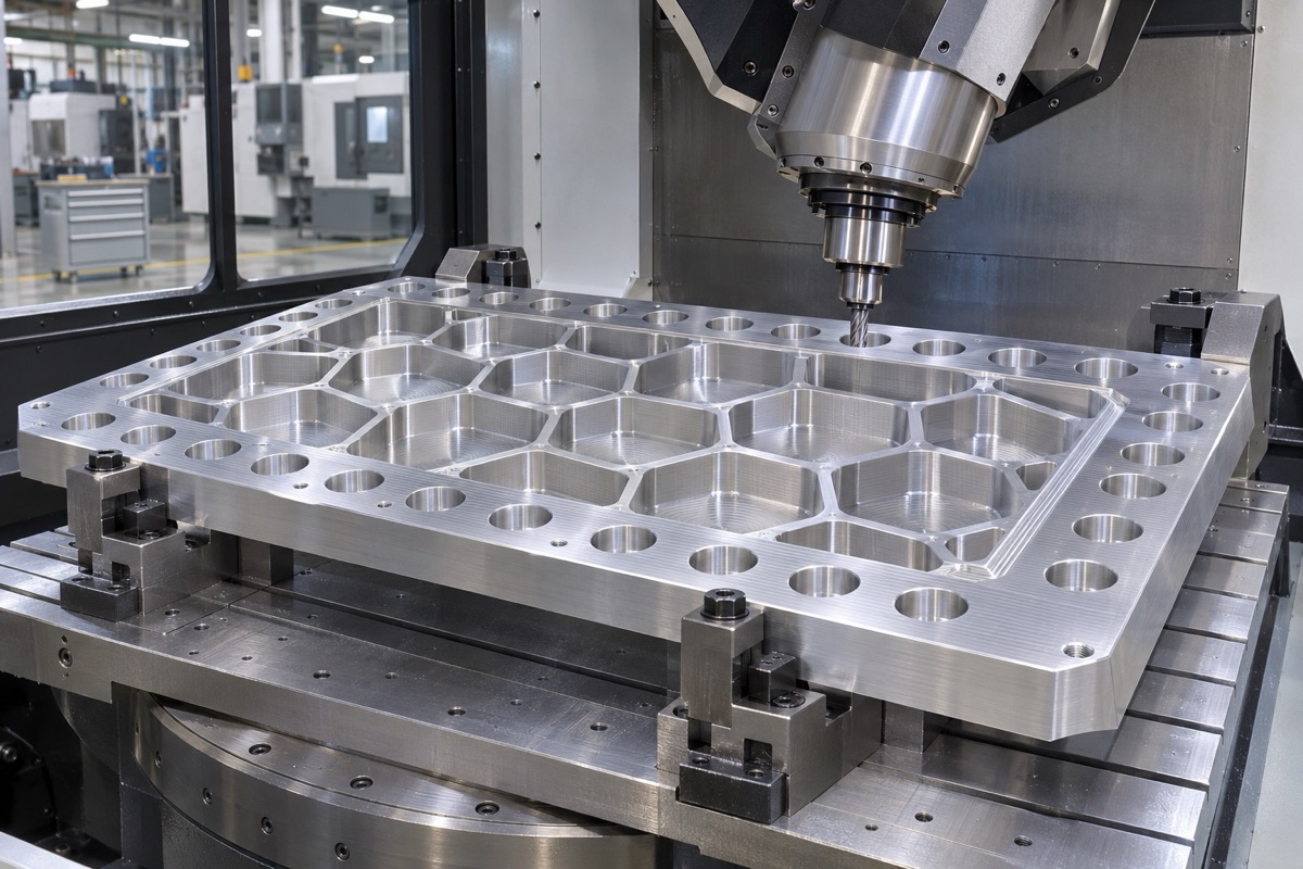
Zoned, symmetric stock removal helps limit distortion in large honeycomb structures.
Machine holes from functional datums
Damping holes near thin walls or cavities can show exit burrs, edge collapse and chatter. Diameter alone is insufficient: verify position, axis direction, edge condition and remaining wall thickness relative to the same datums used for installation.
Link geometry to dynamic validation
Flatness and interface geometry are necessary but cannot prove damping. Record support points, payload, excitation, sensor layout, frequency range and stabilization rules. Acceptance limits must come from the approved platform-level test plan, not from a universal number detached from table size and use.
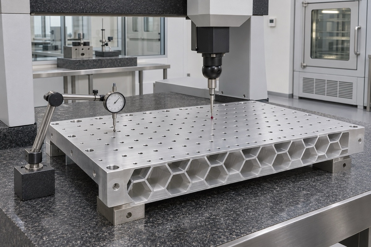
Working-surface geometry must be checked in the specified supported and free states.
Summary
A reliable damped optical table combines low-distortion machining, defined support conditions, traceable interface geometry and project-specific dynamic testing.
FAQ
Do smaller honeycomb cells always improve stability?
No. Cell size, face sheets, material, joining and boundary conditions all affect stiffness and modes.
Does working-face flatness prove damping performance?
No. Flatness is geometric; damping also depends on modes, supports, payload and damping elements.
Can inspection use any three support blocks?
No. Support locations can change the shape of a large structure and must be specified.
Ready to get a quote for your CNC machined parts?
Submit your engineering drawings to qiancj@oemach.com. We support prototype sampling and small-batch production with strict tolerance control.