
Separate the carrier from spirometer performance
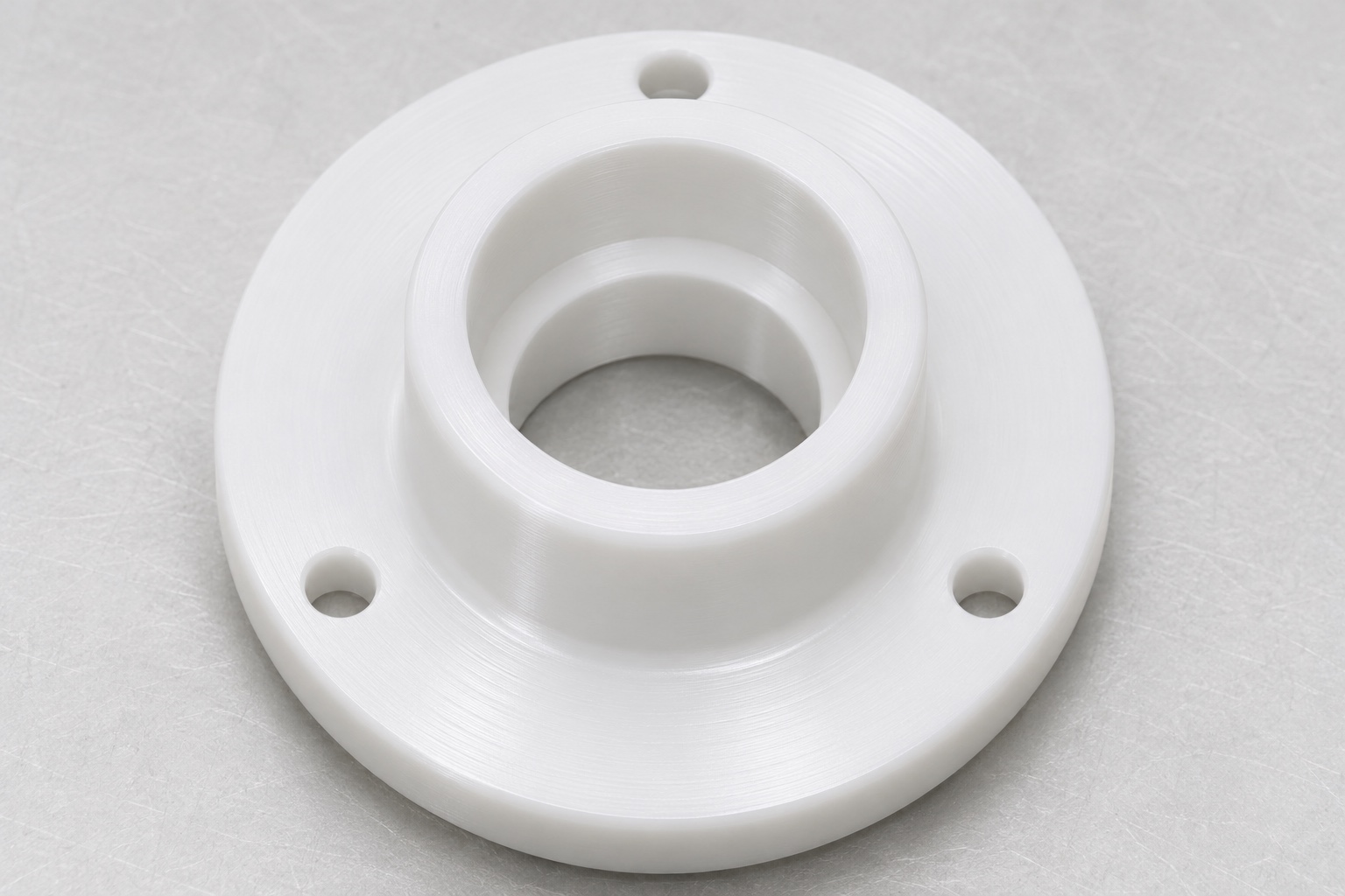
POM-C CNC machining for a spirometer turbine bearing carrier concerns a defined mechanical component, not a respiratory measurement result. The representative part is a short annular carrier with a central stepped bore, a broad flange and mounting holes. It provides a context for discussing geometry and manufacturing. The application name does not approve a material for a particular device or establish compatibility with a commercial spirometer. This guide offers no clinical testing, calibration or repair procedure. The responsible device organization must define the interfaces, loads and acceptance conditions before a supplier can quote a verifiable custom plastic part.

Identify the actual bearing interface
Clarify whether the central feature receives a bearing, a sleeve or another specified reference. The supplier should not select a bearing arrangement from a general description of a turbine. Provide the approved mating geometry and identify which bore region locates the mating component. An entry chamfer and a relieved region are not interchangeable with the useful locating length. A diameter callout alone may not describe the complete seating interface. State the relevant axis, shoulder and required relationships explicitly. This allows manufacturing and inspection to discuss a defined mechanical interface rather than silently assume a fit based on a familiar bearing size.
Define the stepped bore and axial shoulder
The bore step needs a location and a useful annular contact band, together with an allowed corner condition. Overall cavity depth does not prove that a mating reference reaches the intended shoulder. Identify any approved relief or radius where the bore diameter changes. Tool access and inspection access should both be reviewed before production. A probe that contacts a transition can produce a depth reading that does not represent the axial seat. Keep shoulder position, bore diameter and locating length as distinct characteristics. The drawing should make clear which surfaces actually control position and which exist only to provide clearance.
Relate mounting holes to the functional opening
The flange and mounting holes position the carrier relative to its surrounding structure. Their relationship to the central opening should be defined using the approved reference scheme. A set of individually acceptable hole diameters does not establish the complete mounting pattern. Identify useful seating areas and any permitted recesses for fasteners. The intended mounting hardware and condition belong in the interface definition rather than being chosen by the machinist. Do not use arbitrary screw tightening to force a polymer flange into a convenient shape. Acceptance should describe the required free or mounted condition so different inspection setups remain comparable.
Confirm the polymer grade and stock condition
State POM-C explicitly where that is the approved material, including the relevant grade, stock form, colour and documentation requirements. Do not assume that all acetal grades or stock products are equivalent. Review the supplier's material information for the specified product rather than transferring generic properties to an unknown blank. Material identity alone does not establish biological evaluation, cleaning compatibility or suitability within a breathing-gas path. Those are separate device requirements. The manufacturing package should identify the final acceptance state and any conditioning instructions so a dimensional comparison is not made between parts in different, undocumented states.
Plan material removal and support together
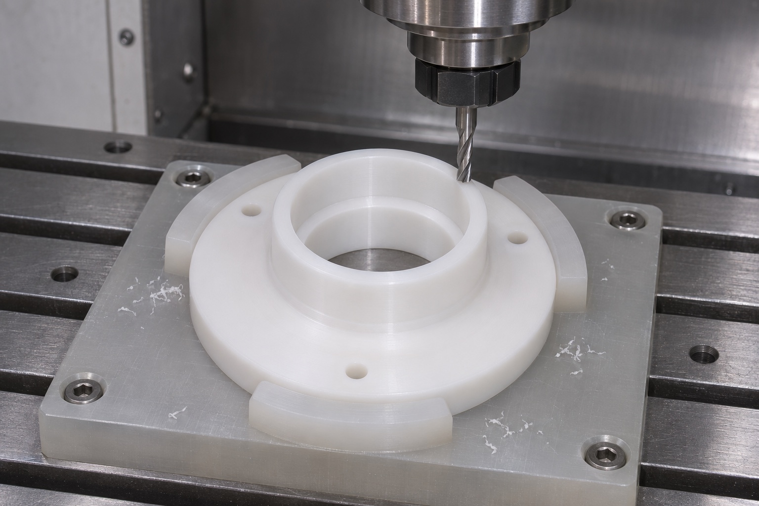
The process review should consider how the central opening, flange and surrounding wall are generated while the part remains supported. The actual route depends on dimensions, stock and equipment; no universal feeds, speeds or stress-relief schedule are proposed. Identify when useful reference surfaces become available and how they are recovered after transfer. Large changes in remaining section should prompt a support review rather than an assumption that the blank behaves like the finished ring. A process plan is not evidence of final conformity. Relevant characteristics still need checking in the approved condition after operations that may influence their measured form.
Avoid hiding form changes with the fixture
A carrier held tightly in a fixture may not have the same observed form after release. Review the contact area and support beneath the flange before selecting clamps or jaws. The fixture should provide access without treating deformation under arbitrary pressure as a manufacturing correction. If the drawing requires a specified assembled condition, distinguish that setup from ordinary machining support. Record the approved method and the reference identity. When readings differ between setups, investigate support and reference recovery before removing additional material. The goal is a reproducible component against controlled requirements, not a passing reading created by a convenient constraint.
Finish bore entries without altering support bands
Remove raised material and loose chips at the bore entry, shoulder access, mounting holes and flange perimeter using an agreed method. Edge finishing must preserve the useful locating length and shoulder contact band. A smooth entrance does not establish the condition of deeper surfaces. Check access for inspecting the finished bore before committing to a production route. Any approved marking should avoid working contacts and remain readable without trapping loose material in the opening. Ordinary chip removal and protective handling must not be described as a validated medical cleaning process, and a closed bag must not be presented as proof of sterile supply.
Select dimensional checks for the geometry
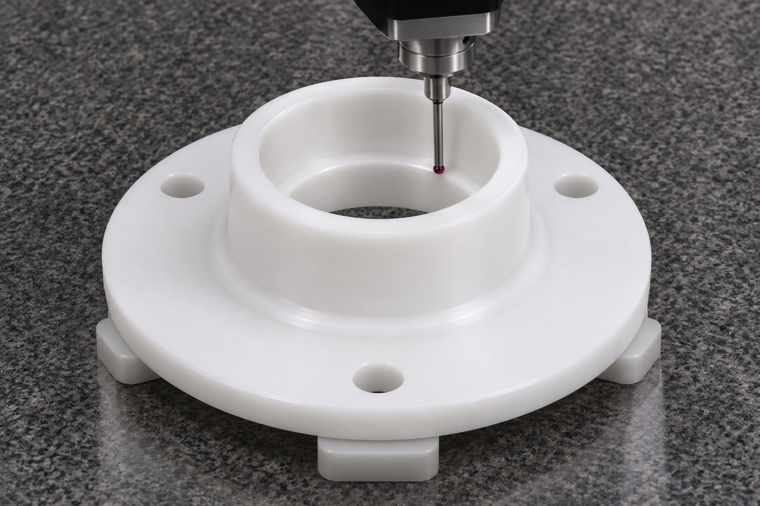
The inspection plan should separate bore size, step depth, shoulder position, flange form and mounting-pattern relationships. Select methods that can reach the useful surfaces with an appropriate reference scheme. A local bore reading cannot establish every relationship to the mounting pattern. A depth reading needs a defined starting face and contact region. Optical, coordinate or contact methods each require an understood scope and a defined part state. Record revision, material and condition with the results. This guide publishes no invented tolerances or inspection values; acceptance limits and actual evidence must come from the approved order and identified manufactured parts.
Limit an inert reference trial to its observation
An identified inert bearing reference or approved stepped mandrel may help locate contact without installing a turbine or operating a spirometer. Record its geometry, support and insertion direction. Do not force a reference through an unexplained obstruction. A geometric seating observation does not establish rotor friction, airflow behaviour, measurement accuracy or calibration. Those matters require separate system requirements and evaluation. Keep reference identity associated with the observation so that replacing a reference does not silently change the meaning of a comparison. A supplier should report what was observed rather than turn a limited dry fit into a broad device-performance statement.
Investigate discrepancies before changing the fit
If a reference appears tilted or stops short, review flange support, bore entry, internal corner condition, reference alignment and the drawing interpretation. Enlarging the entire bore could hide a local obstruction while changing the intended locating interface. Preserve the first observation before authorized correction. Determine whether the issue is a manufacturing deviation or an incomplete interface definition; the required decisions are different. Any changed requirement should have a controlled revision. Reinspect affected characteristics after approved work and retain the record of the reference used, rather than describing a passing trial under a new setup as equivalent evidence.
Quote and package a defined medical plastic part
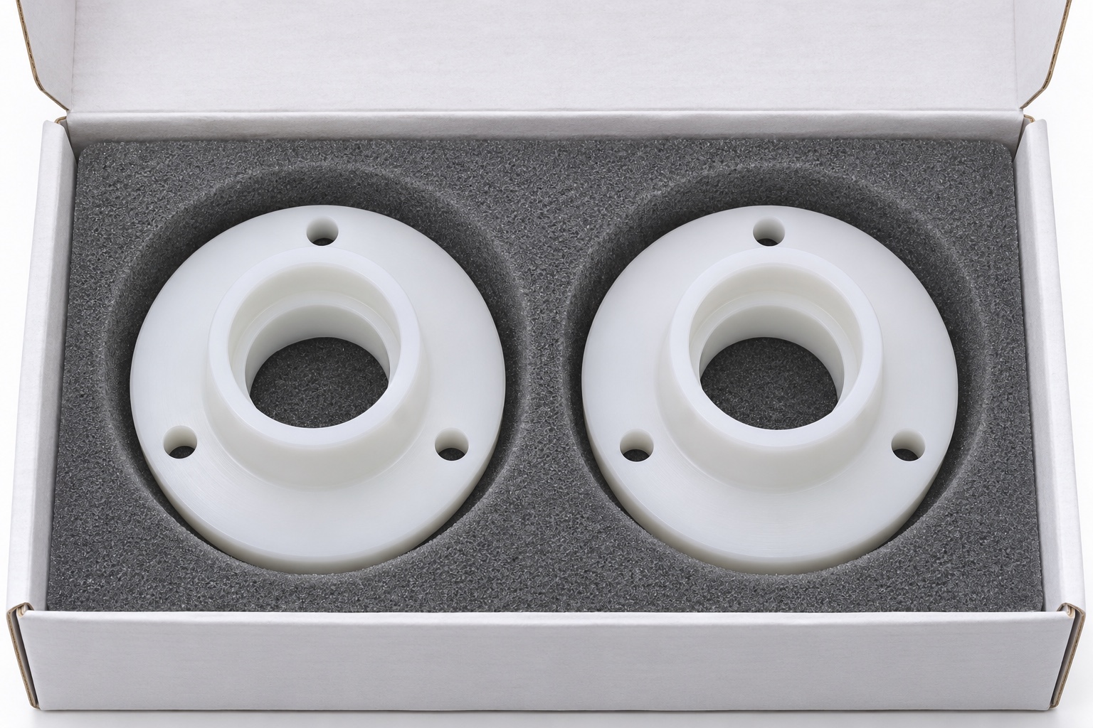
An effective RFQ includes consistent model and drawing, revision, approved POM-C grade, stock or colour requirements, quantity, final state, bore and shoulder definitions, mounting references, inspection scope and protective packaging. Add mating geometry where it governs contact. Separate carriers so flange edges and useful bore surfaces cannot strike neighbouring parts during transport. Packaging should support the part without loading the flange into a different shape or leaving fragments in the central opening. Keep identity and inspection evidence associated with the parts. This creates a precise machining enquiry while leaving medical qualification and spirometer performance with the responsible device organization.
FAQ
Does the carrier material name approve it for a breathing-gas path?
No. Material identity does not establish device suitability, biological evaluation or cleaning compatibility. The responsible organization must define and verify those requirements separately.
Is a bore diameter enough to define the bearing seat?
Not necessarily. Useful locating length, axial shoulder, transition condition and relationships to mounting references may also require definition and inspection.
Why distinguish free and mounted inspection states?
Support and fastening can influence a polymer component. The approved state must be recorded so fixture-induced changes are not mistaken for acceptable free-state geometry.
Can a smooth bore entry prove the shoulder is acceptable?
No. The deeper contact band and its position need an appropriate inspection method. An entry check cannot establish every internal surface.
Does an inert reference trial prove spirometer accuracy?
No. It records geometric contact only, not rotor behaviour, airflow performance, measurement accuracy or completed calibration of the device.
What belongs in the supplier enquiry?
Send approved files, material grade, quantity, final state, bore and mounting definitions, relevant mating geometry, inspection evidence requirements and protective packing instructions.

tanghangyun@oemach.com