
Define the bush before discussing the instrument
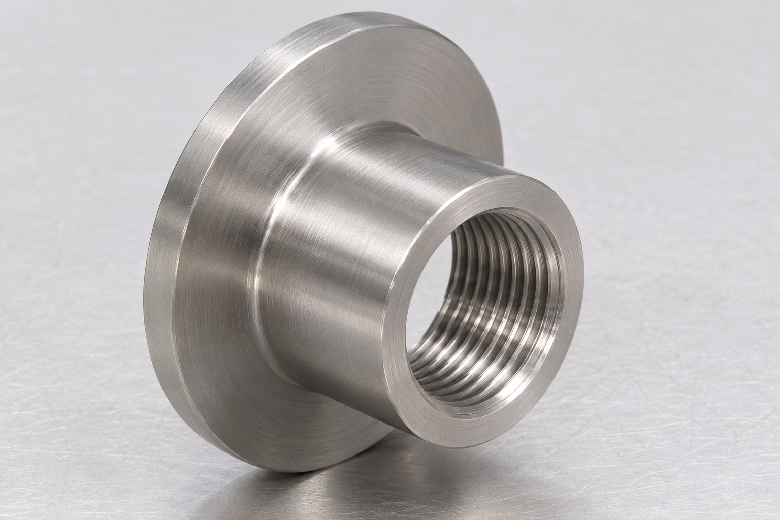
316L CNC turning for a microtome clamp threaded bush starts with a controlled mechanical definition. The representative component is a short flanged cylinder with an internal through thread and a plain locating outside diameter. Its name places it within a laboratory instrument, but does not approve a replacement or establish compatibility with any commercial microtome. This guide addresses machining and dimensional inspection only. It gives no blade-handling, sectioning, adjustment or repair instructions. The responsible instrument designer must define the interfaces and acceptance requirements. A supplier should quote the specified bush rather than infer an entire clamp mechanism from a photograph or an application label.

Specify the internal thread completely
A thread description should identify its system, nominal size, pitch, direction, tolerance class and required useful engagement length. State the accepted drawing convention and whether a model shows actual or simplified thread geometry. An unthreaded hole in a model must not be interpreted as permission to choose a convenient tap. Distinguish the thread's functional length from entry chamfers and any runout or relief. A mating screw that turns into the first few threads does not establish the complete requirement. Agreement at quotation stage prevents different suppliers from pricing physically different interfaces while using the same general description of a threaded medical component.
Relate the thread axis to the locating diameter
Identify which cylindrical surface locates the bush in its surrounding component and how the thread is related to that reference. Outside diameter size and thread acceptance are separate checks; passing both individually does not establish their mutual alignment. The inspection plan must address any specified positional or orientation relationship with an appropriate method. A thread's effective reference cannot simply be replaced by an arbitrary smooth drilled surface. If the design uses a mating reference, identify it and its approved geometry. Do not invent a universal coaxiality tolerance: the controlled drawing and the intended measurement definition determine what must actually be verified.
Separate the flange seat from overall length
The flange may provide an axial seating surface while the smaller cylindrical body provides location. Identify the useful annular contact area, the opposite face and any transition relief. Total length does not establish flange thickness, seating orientation or the shoulder location independently. A rounded transition must not hold the bush away from its intended seat. Supply the approved mating corner condition where it determines contact. The supplier needs enough information to distinguish a decorative flange from a functional stop. Keep each acceptance characteristic linked to its reference so convenient caliper readings are not substituted for a required face relationship.
Confirm material and final condition
State the required 316L material specification, stock form and documentation scope. Do not infer alloy identity from a polished surface or assume that another stainless grade is an acceptable substitute. Identify any approved treatment, marking or special cleaning requirement and the dimensions that apply after it. This article makes no claim about biocompatibility, corrosion testing, sterilization or suitability for patient contact. Material selection for an instrument remains a separate responsibility. The manufacturing record should distinguish the material received, the operations performed and the final state accepted, so measurements from an intermediate stage are not accidentally used as final evidence.
Plan turning with explicit transfer references
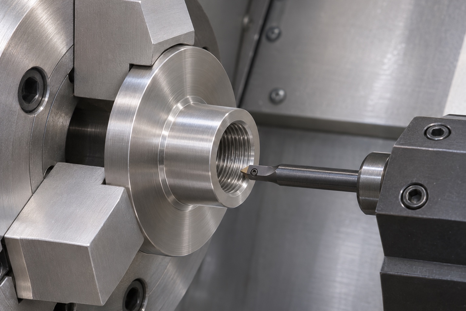
Review how the flange, locating diameter, bore preparation and thread can be produced while maintaining access and support. The actual sequence depends on the approved dimensions, stock and equipment. It is not determined by the product name. Features produced in one setup may simplify reference transfer, but setup count alone is not proof of conformity. If the component is reversed, identify how the finished reference is recovered without damage. Keep a clear distinction between machining support and inspection support. A fixture that is convenient for cutting may obscure the flange face or constrain the part in a way that is unsuitable for final acceptance.
Choose a thread process for the actual geometry
Tapping, single-point turning or another approved thread process must be reviewed against size, access, useful length, exit condition and the remaining wall. No universal cutting speed or engagement allowance is proposed here. The supplier should resolve tool access and chip evacuation before committing to a route. A through thread still needs a defined entry and exit condition. Burrs at either end can influence an apparent fit without changing the intended nominal thread. Identify how finishing will preserve the useful profile and how affected features will be rechecked. Process feasibility does not authorize a change to a controlled interface.
Protect finished seats during secondary operations
Gripping a finished locating diameter can mark it or alter the observed form. Supporting only the flange edge may influence a thin contact region. Review contact area, support and the required inspection state before selecting workholding. Do not use excessive fixture force to make an interface appear acceptable. Where acceptance requires a specified assembled condition, reproduce that condition using approved references rather than arbitrary clamping. Record differences between constrained and released readings when they are relevant. If readings disagree, review support, temperature state and reference recovery before removing more material from a part that may already satisfy the actual definition.
Distinguish thread gauging from geometric inspection
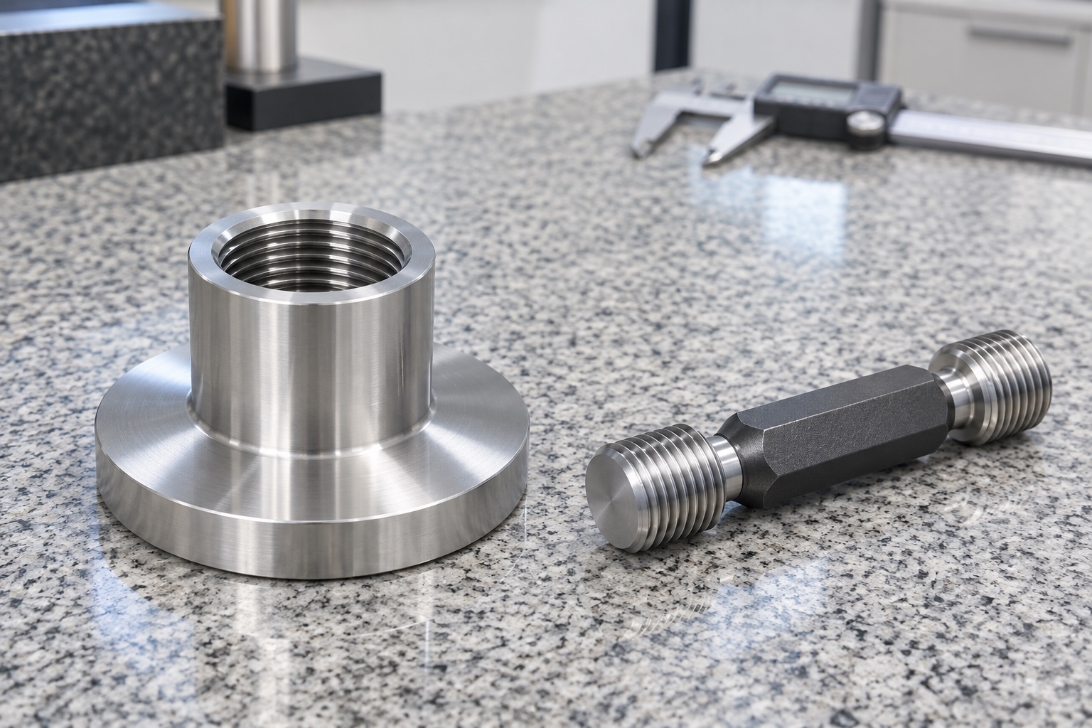
The inspection plan should assign a method to each characteristic: thread acceptance, locating diameter, flange dimensions and any relationship between the thread and the seat. An appropriate thread gauge addresses its defined scope; it does not automatically verify every face and axis relationship. Record the gauge identification and the applicable thread requirement. Separate any dimensional measurement from observations made using an identified mating reference. Do not publish invented tolerances or claim an inspection result before measuring identified parts. A useful report makes clear what was checked, against which revision, in what state and with what acceptance criteria.
Use an inert fit reference without overstating it
A documented inert screw or mating reference can help observe entry, usable engagement and seating without assembling or operating a microtome. Do not force it through an unexplained stop or use an actual cutting instrument as an improvised gauge. Record the reference identity, orientation and observed contact. A fit observation does not establish clamping force, wear life, section thickness accuracy or safe instrument operation. Those questions require separate requirements and evidence. Keep the supplier's geometric observation distinct from system qualification, and avoid reporting an unrecorded hand-fit trial as proof that a manufactured bush is an approved spare part.
Diagnose an early stop before recutting
If an identified reference stops unexpectedly, inspect entry edges, thread definition, useful length, alignment and possible interference at the flange transition. Enlarging a bore or recutting a thread without a diagnosis may remove the symptom while changing a conforming interface. Preserve the initial observation and identify affected characteristics. A manufacturing deviation needs an authorized disposition; an incomplete design needs clarification or revision. Those are different decisions even when the symptoms look similar. Repeat the relevant inspections after any approved correction, and retain the earlier evidence so the change is traceable rather than hidden by a final passing fit.
Prepare an RFQ and protect the delivered geometry
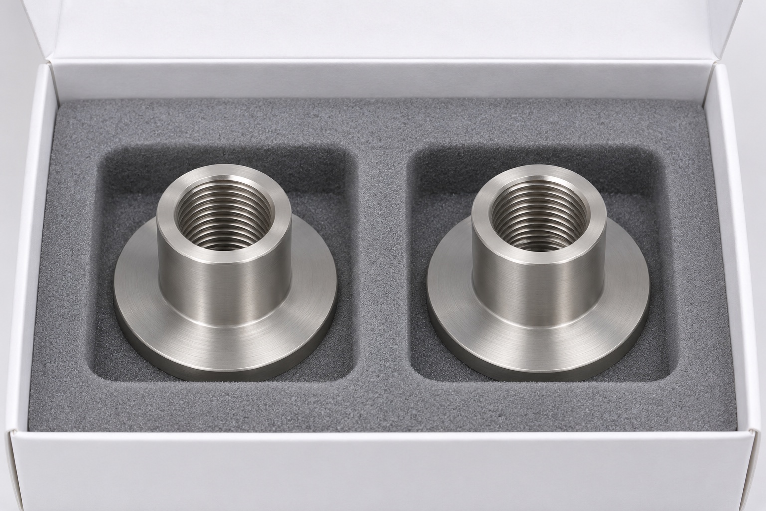
A complete request includes approved model and drawing, revision, material specification, quantity, thread designation, useful engagement, locating reference, flange contact area, final condition, inspection scope and packaging requirements. Include approved mating geometry where it controls seating. Separate bushes so threads and locating diameters cannot strike adjacent metal parts in transport. Protective packing must not shed material into the bore or load a delicate flange edge. Keep identification associated with the parts without obscuring working surfaces. This approach makes medical precision machining quotations comparable while leaving instrument approval and operating performance with the responsible organization.
FAQ
Is a threaded bush with the same outside diameter interchangeable?
No. The thread, useful engagement, flange seat and their relationships also need an approved definition. Similar appearance or outside size does not establish replacement approval.
What information belongs in a thread designation?
Specify the thread system, nominal size, pitch, direction, tolerance class and useful engagement, together with the drawing convention and any entry, exit or relief requirements.
Does a passing thread gauge verify flange alignment?
Not by itself. Gauging has a defined scope. Face orientation and the relationship to locating surfaces require separate checks where specified.
Can turning everything in one setup replace final inspection?
No. A shared setup can simplify reference transfer, but it does not demonstrate conformity of the final part after subsequent operations.
Does an inert screw fit prove microtome performance?
No. It records a limited geometric observation, not clamping capability, service life, sectioning accuracy or safe instrument operation.
What should accompany a machining enquiry?
Provide approved files, material, quantity, thread and datum definitions, final condition, inspection requirements, mating geometry where relevant and protective packaging instructions.

tanghangyun@oemach.com