
Define the retainer without implying console approval
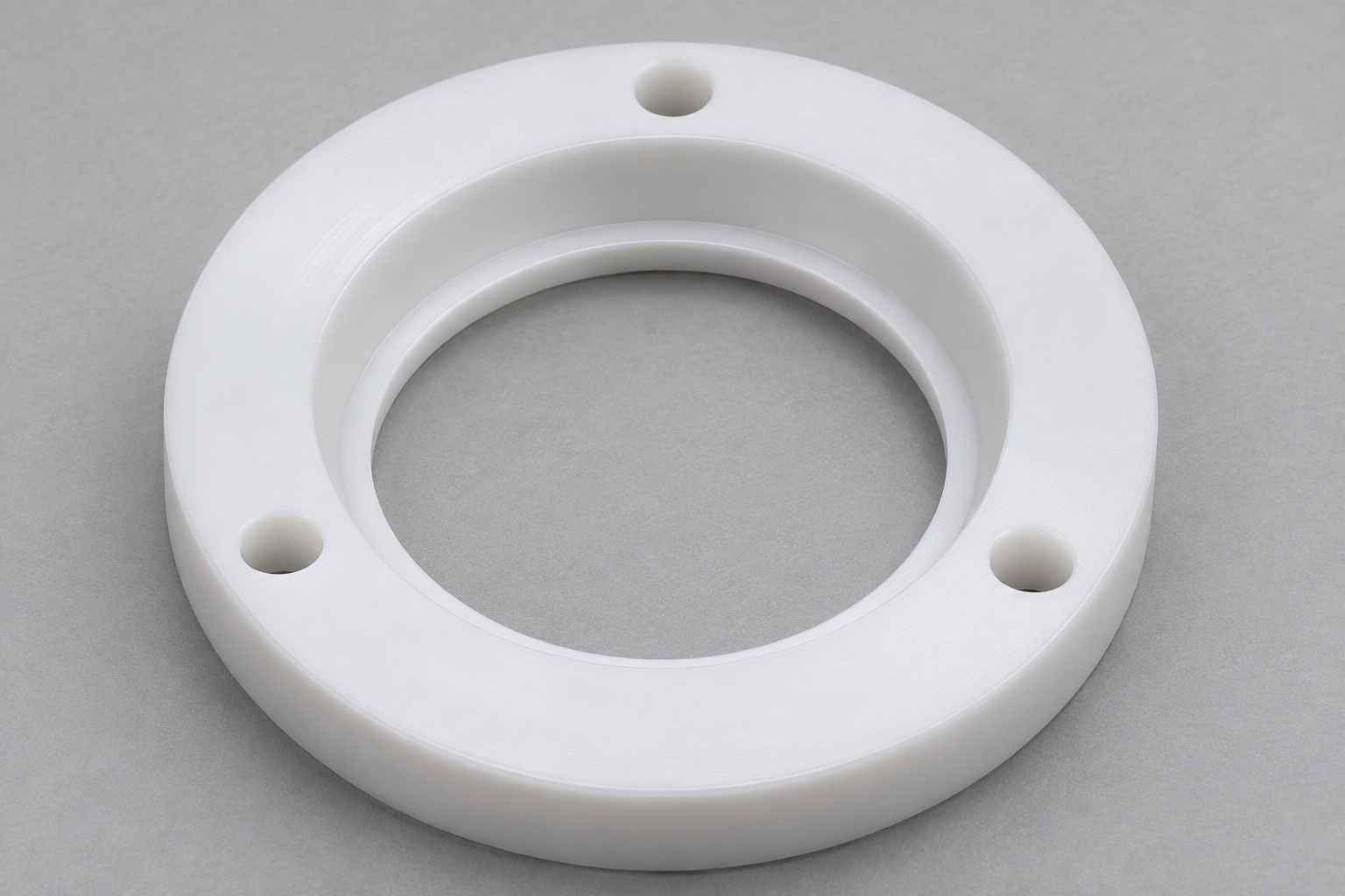
POM-C CNC machining for an ultrasound console trackball retainer concerns one mechanical ring in a separately defined control assembly. A central opening, an internal lip and an outer mounting flange may establish contact or clearance. This guide addresses how those features are specified and inspected. It does not define the complete trackball mechanism, sensors or console electronics. Correct ring geometry does not establish input accuracy, electrical safety or ultrasound image quality. The device owner must supply the intended assembly and acceptance requirements. A component drawing should therefore describe real interfaces rather than rely on the application name to imply compatibility with a commercial console.

Identify the opening and useful lip region
Distinguish the visible opening diameter from the larger internal step and the useful lip that controls the mechanical interface. The surfaces can have different functions and should not be accepted by a single arbitrary diameter reading. Specify the actual profile, transition condition and axial position. If a curved interface is required, define it explicitly instead of expecting the supplier to infer a sphere from the word trackball. The representative geometry discussed here uses a defined stepped opening, not a universal ball-retention design. Approved mating geometry is needed wherever it determines contact. An image alone cannot establish those details or the allowable clearances.
Set the seating face and lateral references
Choose the ring face that seats against the housing and identify how the assembly locates it laterally. The outside perimeter need not be the functional reference. Relate the opening, lip and mounting pattern to the approved datum scheme. A drawing should let inspection recover those references without a powered console. If selected pads contact the housing rather than the whole flange, show them. Otherwise, two setups can support the same ring differently and produce apparently conflicting measurements. Establishing the reference scheme before manufacture is more useful than trying to explain after delivery why a convenient granite contact did not represent the intended mounting condition.
Relate lip height to the final assembly space
Specify the lip's useful width and height separately from total ring thickness. Identify any regions that must remain clear for an approved inert mating envelope. A correct outside thickness does not prove that the internal step is positioned correctly. Review transitions and tool access before selecting the machining route. If an entry chamfer or relief is proposed, confirm it will not remove the working lip or change the available space. That decision needs design approval. Do not substitute a hand-smoothed edge for a defined profile, because a small unrecorded change can make later dimensional comparison difficult even when a trial piece appears to move freely.
Define mounting holes as a related pattern
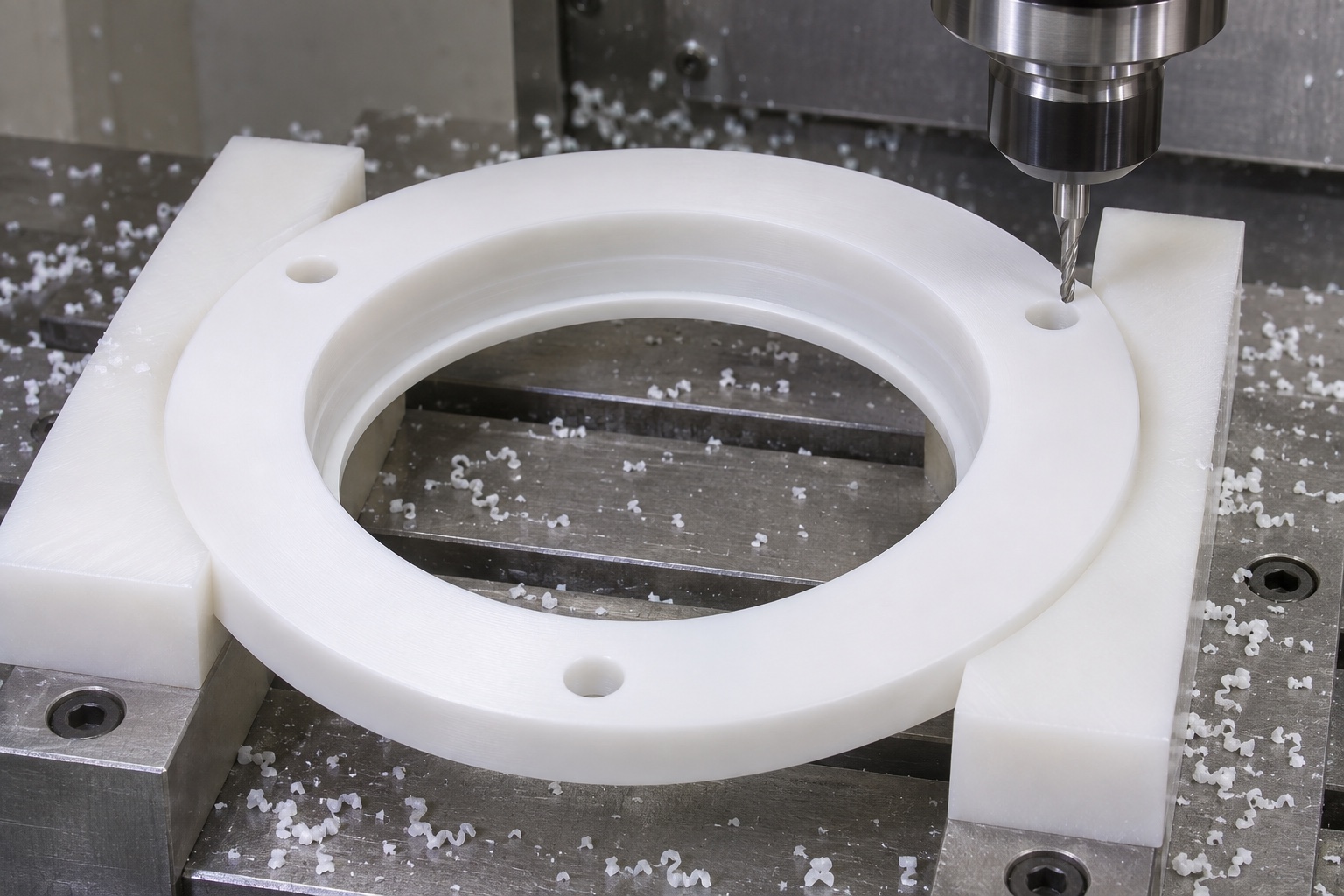
Mounting holes must be positioned relative to the functional opening and housing references, not merely drilled to an individual diameter. If counterbores or fastener recesses are included, define their seats and remaining sections. A fastener that passes through a hole does not verify the complete pattern or the final ring position. The intended hardware and assembly condition require separate definition. Do not apply arbitrary screw tightening to force the polymer into an apparently acceptable shape. The manufacturing package should identify access for cutting and edge finishing as well as how the hole pattern and seating surfaces will be evaluated in the specified condition.
Specify POM-C rather than a generic white plastic
State the requested grade, stock form and documentary scope. POM-C and another acetal grade are not automatic substitutes, even if both appear similar. Material identity and any required conditioning or storage instructions should remain associated with the controlled revision. This guide does not establish suitability for a cleaning chemical or a medical electrical device from the material name alone. Special cleaning and final surface requirements need their own approved specification. Likewise, a universal heat-treatment recipe is not appropriate for every polymer component. The actual material, geometry and acceptance condition govern those decisions, and the supplier should identify unresolved requirements before quotation.
Plan material removal with ring support in mind
Creating the large opening and inner step changes the section available to support the flange. The process review considers when each region is cut, where the part is held and how the reference surfaces survive transfer. Turning and milling may both be considered according to actual geometry and equipment; the name retaining ring does not prescribe a universal route. Avoid treating a process suitable for a thick disk as automatically suitable for a thinner stepped flange. The plan should explain tool access and reference continuity without inventing feeds, cycle times or capability. Subsequent operations need checks appropriate to features they could alter.
Distinguish clamping effects from the required shape
Contacts used for workholding can influence a polymer ring, especially where the opening leaves limited material around mounting features. Support useful regions without forcing the flange into a shape chosen by the fixture. The drawing should identify whether acceptance is in the free state or a defined mounted condition. If mounted-state measurements are required, reproduce that approved condition with identified hardware and support. A temporary vise or arbitrary screw load is not automatically equivalent. Before correcting a difference in readings, review references, contact force and material condition. The aim is to measure the specified part state, not an undocumented effect introduced by the test setup.
Finish entries and preserve the lip definition
Remove loose material from the opening, lip transition, mounting holes and accessible recesses with an agreed method. Do not round away the useful lip or alter its height under a generic instruction to make the part smooth. Inspect affected geometry after finishing steps capable of changing it. A clean-looking outside surface does not prove that internal transitions contain no fragments. Resolve limited access before manufacturing. Ordinary chip removal is different from a validated cleanliness process and cannot demonstrate sterile delivery. Define any special handling or residue requirements separately so the dimensional report and the cleaning evidence are not confused with each other.
Choose measurements that answer separate questions
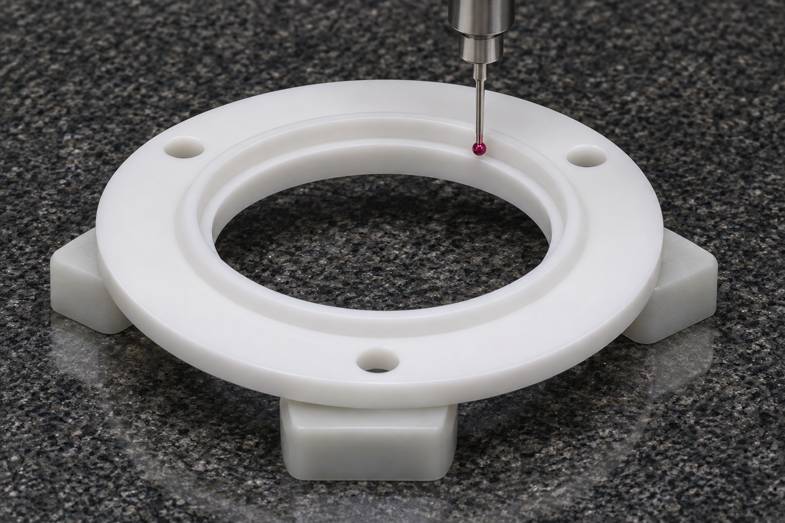
The inspection plan should distinguish opening size, internal step geometry, lip position, flange seating and mounting-pattern relationships. A passing ring or ball reference cannot verify all those characteristics. Select methods that reach the actual surfaces without unnecessary deformation and specify the reference section used for a profile reading. A coordinate or optical setup still needs a controlled datum scheme and documented support. Record material condition and revision. This article gives no invented tolerances or measured results. Real acceptance requires evidence from identifiable components, and any region not covered by the selected method must be stated rather than assumed conforming.
Limit an inert comparison to observable geometry
An identified non-electrical reference can help observe local contact and clearance without installing a ring in a clinical console. Record its geometry, orientation and support. Do not use force to overcome an unexplained interference or report a trial movement as proof of complete trackball performance. The observation cannot establish operating feel, wear life, sensor accuracy or suitability for clinical use. Those require separate assembly evaluation. Keep the reference identity with the result so a later comparison is reproducible. If the reference behaves differently when the ring is constrained, investigate that state difference before removing material from the lip.
Protect the ring and prepare the quotation package
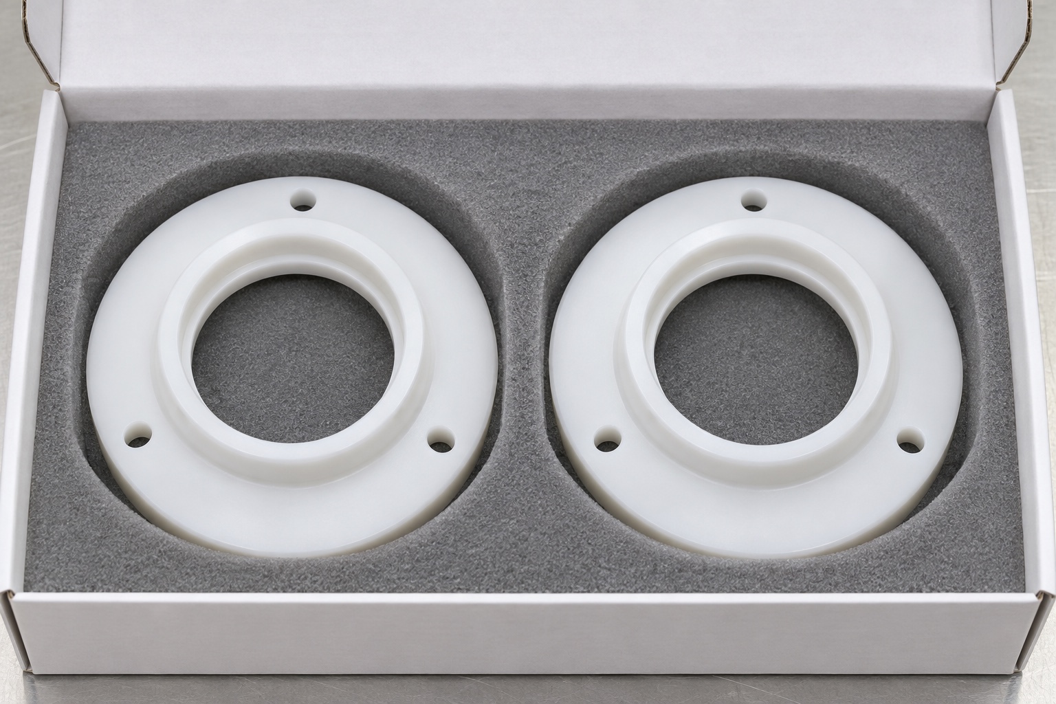
Separate retainers during transport and support the flange without pressing on the inner lip. Avoid packing fragments in the stepped opening or screw recesses. Maintain revision and material identification outside functional contact areas. A complete inquiry includes consistent drawing and model, exact grade, quantity, final surface state, reference scheme, lip profile, mounting pattern, acceptance condition, inspection scope and packaging instructions. Add approved mating-envelope information where it governs clearance. These inputs let a medical console parts supplier quote a verifiable machining scope. They do not transfer qualification of the trackball assembly, console electronics or ultrasound system to a dimensional fit check of one polymer ring.
FAQ
Does one opening diameter fully define the retainer?
No. The internal step, useful lip profile, height, seating face and mounting relationships need separate definition. An isolated diameter check cannot verify the complete interface.
Should the supplier infer a spherical surface from the name trackball?
No. Any required curved profile must appear in the approved geometry. The application name and a photograph do not define contact shape, clearance or compatibility with a console.
Can mounting screws be used to force a ring flat for inspection?
Not arbitrarily. Acceptance follows the specified free or mounted condition. If a mounted state is required, its hardware, support and relevant procedure must be defined and reproducible.
Is POM-C automatically approved for medical cleaning?
No. The material family and appearance do not establish chemical compatibility or a validated cleaning process. Requirements and evidence must be defined for the actual material and intended conditions.
Does an inert reference moving freely prove trackball performance?
No. It shows a limited geometric observation under recorded conditions. It cannot establish sensor accuracy, operating feel, wear life or clinical suitability of the complete assembly.
What information should be included in the RFQ?
Provide controlled files, material grade, quantity, final condition, references, lip and mounting definitions, inspection state and evidence, packaging requirements and approved mating geometry where it controls fit.

tanghangyun@oemach.com