
Define a mechanical support interface
6061 CNC milling for a retinal camera mount dovetail shoe concerns the connection between a support component and a separately specified rail. Angled flanks can locate the shoe, while a split region and screw feature may form part of a defined clamp arrangement. This guide addresses the geometry and inspection of the machined component. It does not establish camera stability during imaging, holding force, patient support or diagnostic image quality. The equipment name identifies the application context, not compatibility with a commercial camera. The owner must define the actual rail, loading conditions and required system evidence separately from the supplier's dimensional inspection of the shoe.

Identify the actual dovetail contact surfaces
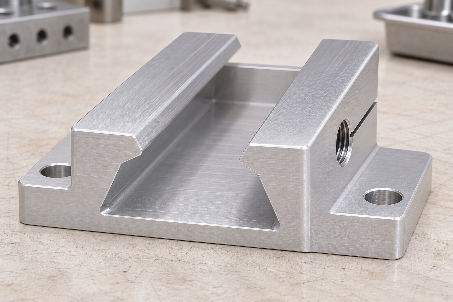
Determine whether both angled flanks locate, whether one is a clamp contact and whether a base surface is intended to seat or remain clear. Do not assume every visually similar dovetail uses the same contact scheme. The drawing should distinguish working bands from corner relief and entry chamfers. A width measured across an arbitrary edge may not describe the functional interface. Specify the section and reference height used to define the profile. If the rail sets the functional geometry, provide its approved definition or an agreed reference method. This makes the intended contact recoverable without relying on a worn or unidentified sample rail.
Relate flank angle to a defined section
An angle alone is not a complete dovetail specification. The profile also needs a width convention, useful engagement length, relation to the base and any required orientation to mounting features. A measurement taken at the top can differ from one taken lower on an angled face without either reading being wrong. Agree the section before comparing results. If using pins, balls or an optical profile, define the method and the surfaces it evaluates. Do not borrow a nominal angle from another mount and assume it supplies compatibility. The model and drawing must describe the actual approved interface and any inspection allowances explicitly.
Review corner relief and end entry
The tool route must allow the mating rail to reach the intended contact region without stopping at an unreviewed internal corner or end feature. A milling tool leaves geometry related to its cutting profile and access. Inspect the proposed reliefs against the rail definition rather than enlarging every flank until a trial sample passes. Entry chamfers can help access, but they must not reduce useful engagement below the specified value. Any change that alters contact length or remaining wall section requires design approval. Resolve how the relieved and working regions will be distinguished during inspection so the report does not accidentally measure the wrong surface.
Define the split and screw geometry separately
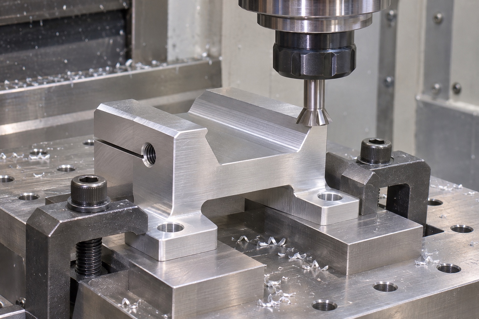
If the shoe has a split clamp region, the drawing must define its width, termination and relationship to the screw. Identify thread identity, clearance-hole requirements, counterbore or head space where applicable. The actual screw and mating assembly also need definition. A passing thread gauge does not prove a clamp force or safe service load. Nor does a visible split establish that deformation under tightening is acceptable. The machining plan evaluates access, remaining sections and edge condition. Any specified tightened-state geometry or assembly check belongs in an approved procedure with known components, rather than being improvised by the supplier during a fit trial.
Specify aluminum condition and final finish
State the requested 6061 material condition, stock form and documentation. A silver appearance does not identify the alloy or an approved surface process. If a coating or other external finish is required, identify masked regions and dimensions that apply in the final state. Functional flank contact can depend on that state, so comparing unfinished and finished parts without saying so can be misleading. This guide does not claim a coating friction value or corrosion performance. Those requirements must be supplied and evaluated separately. Keep material and process identity linked to the drawing revision so later substitutions are not represented as the same approved component.
Plan access for the actual dovetail route
Review the angled feature, nearby mounting surfaces and tool clearance together. Some geometries can be accessed with suitable form tooling; others require a different orientation or an approved route change. The supplier should evaluate the actual section rather than promise that every dovetail is a simple three-axis operation. Tool reach, the approach path and chip exit need consideration before cutting. Establish useful reference surfaces before transferring the part to another setup. No generic feed, speed or cycle time is specified here. A verifiable process plan explains how the flanks and mounting references remain related through the chosen operations and subsequent finishing.
Keep workholding effects visible
A split shoe can respond to clamping, so the fixture should not silently force it into the condition the drawing expects to measure. Identify permitted support regions and whether acceptance applies freely or in a specified assembly state. A temporary vise load is not automatically equivalent to the actual clamp screw arrangement. If a mounted condition is required, reproduce its approved details instead of choosing convenient pressure. Differences in profile readings should prompt review of support, contact and surface state before corrective machining. The purpose is to distinguish the geometry of the released part from a shape created by the manufacturing or measuring fixture.
Finish edges without changing the contact bands
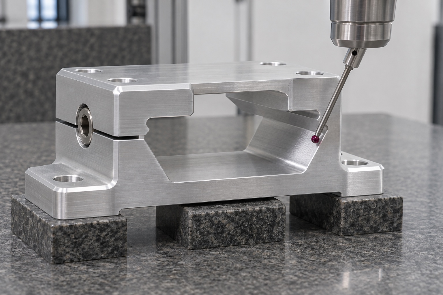
Remove raised material at entries, reliefs, the split and screw features using an agreed method. Do not polish away working flank geometry or round a locating edge without authorization. The inspection plan should include affected dimensions after finishing steps capable of changing them. A smooth entry is not evidence that the entire internal contact is free from loose fragments. Resolve difficult access before production. Ordinary chip removal and protective handling are not proof of medical cleanliness or sterile delivery. If special cleaning or residue requirements exist, define them separately and keep their acceptance evidence distinct from geometric conformity of the aluminum shoe.
Inspect related geometry in the agreed state
Evaluate flank section, useful length, mounting references and screw-feature position according to the approved datum system. Checking an external rectangle does not confirm the dovetail. A profile method can evaluate selected geometry, but it still needs an identified section and support condition. Record final surface state and any features not covered by the selected method. This article gives no invented tolerances or measured results. Actual acceptance must use project requirements and evidence from identifiable parts. That discipline prevents an isolated size reading or an attractive inspection photograph from being presented as confirmation of every contact, orientation and clamp-related requirement on the drawing.
Limit the inert rail comparison to geometry
An identified inert rail reference can help observe entry, seating and local contact without a retinal camera, patient or operating instrument. Record the rail definition, insertion direction, support and any condition imposed on the split region. Do not force an unexplained fit or apply an arbitrary screw torque. The observation cannot establish holding force, vibration behavior, imaging alignment or suitability for clinical use. Those require separate evaluations. If the rail stops early, inspect entry, relief, profile section, surface state and reference identity first. Preserve the original observation so an approved correction can address a known cause rather than merely make one sample slide more easily.
Protect flanks and prepare the machining request
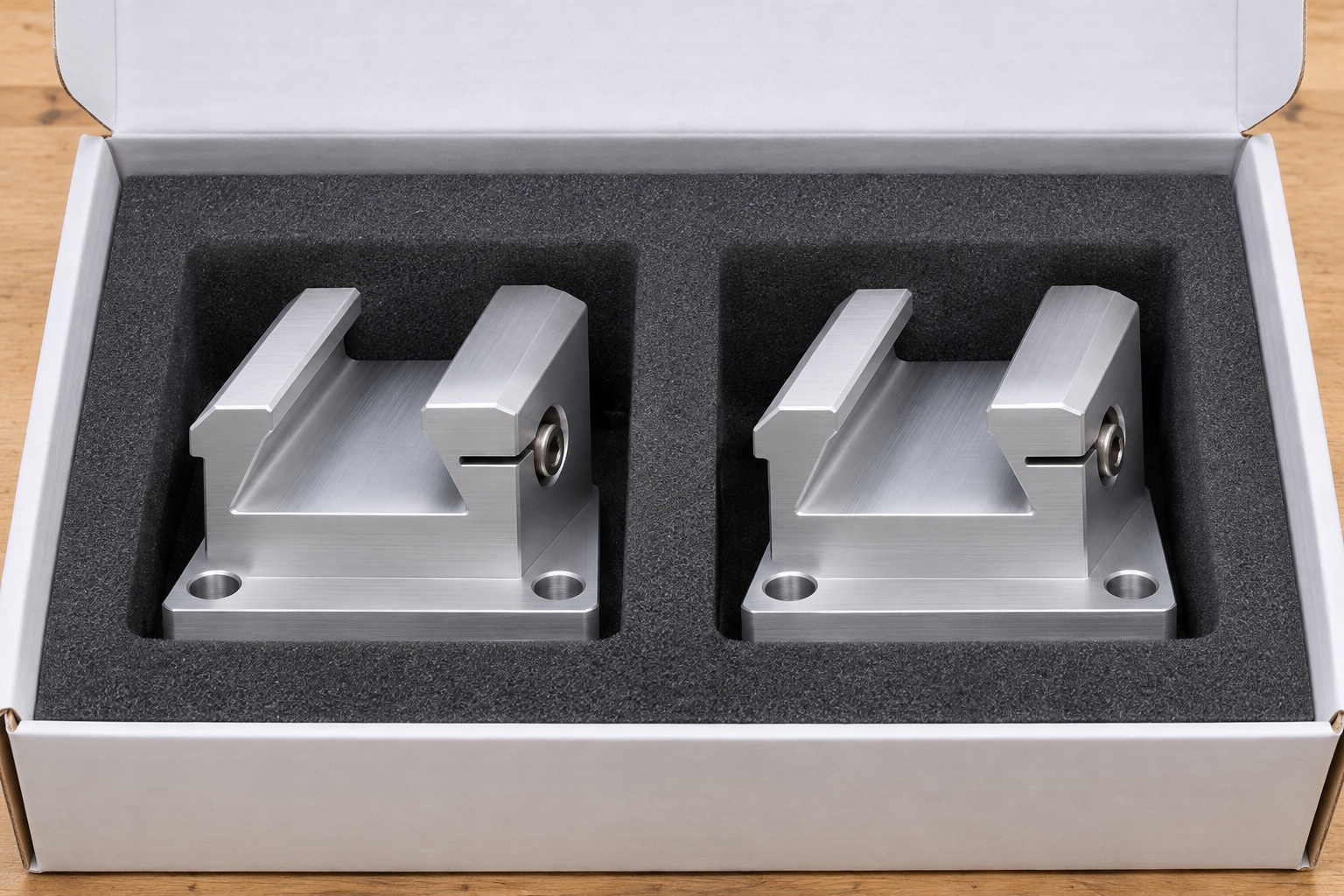
Package shoes separately so working flanks, mounting faces and split edges cannot strike other parts. Use support that does not spread or compress the split region and avoid packing fragments in the screw features. Maintain revision and material identity outside functional contacts. A complete RFQ includes controlled drawing and model, 6061 condition, quantity, final finish, reference scheme, profile definition, screw details, inspection scope and packaging requirements. Add approved rail information where it governs fit. This lets a precision medical equipment machining supplier quote a defined component while the device owner retains responsibility for camera mounting performance and the complete system's intended use.
FAQ
Does the dovetail angle alone define compatibility?
No. Profile width convention, reference section, contact length, relief, orientation and final surface state also matter. Use the approved rail and shoe definitions rather than borrowing an angle from another mount.
Should the base always touch the rail?
Not necessarily. Some designs use it as a seating surface while others provide clearance. The drawing must identify intended contacts, so inspection does not accept or reject a part using an assumed contact scheme.
Does a correct screw thread prove clamp force?
No. Thread conformity is a manufacturing characteristic. Holding force and safe loads depend on the specified assembly, components and conditions, requiring separate approved evaluation rather than a thread check alone.
Can vise pressure represent the mounted state?
Not automatically. The support and loads may differ from the actual assembly. Measure in the specified condition and document it; do not use arbitrary pressure to make a split profile appear conforming.
What can an inert rail trial demonstrate?
Only the recorded geometric contact and entry condition of identified references. It does not establish vibration resistance, imaging stability, holding force or clinical compatibility of a retinal camera mounting system.
What should be reviewed before relieving a tight fit?
Check entry, corner clearance, profile section, final finish, support and rail identity. Any correction needs approval and repeat inspection of affected geometry so the cause is not concealed by undocumented hand work.

tanghangyun@oemach.com