
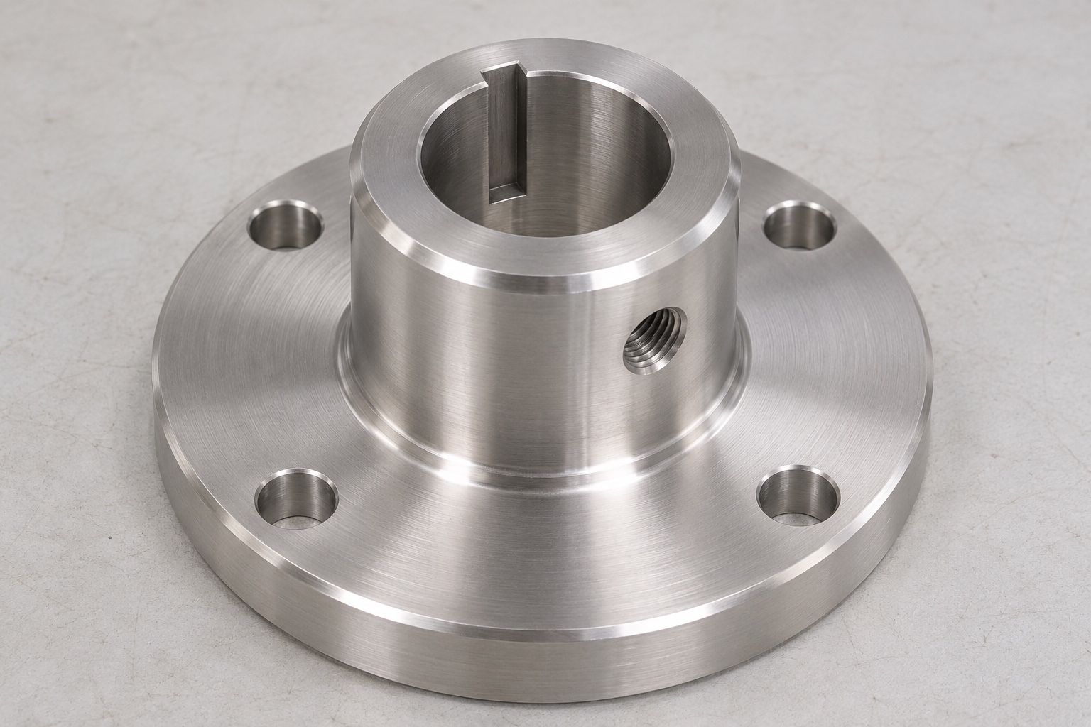
Define the hub as a mechanical interface
316L CNC turning for a medical analyzer carousel hub starts with the connection between a shaft, a flange and the supported rotating structure. A central bore may locate the hub while a keyway controls its angular relationship. Flange holes and a radial screw feature introduce additional relationships that must be specified. This guide addresses manufacturing and dimensional inspection of those features. It does not establish carousel speed, transmitted torque, reagent temperature or assay performance. The term reagent carousel identifies an application context, not proof of compatibility with a commercial analyzer. Keep component acceptance separate from validation of the complete instrument and its operating process.

Choose the locating bore and axial reference
Identify the bore region that actually locates on the shaft and the flange face that establishes axial seating. Entry chamfers and relieved areas should not be mistaken for usable contact length. The largest outside diameter is not automatically the functional datum. A drawing should enable the inspector to reconstruct the working axis and seating plane without an undocumented assembly. If another part determines the actual reference, supply its approved geometry or a defined reference method. Relate flange and keyway requirements to those references rather than to whichever exterior surface happens to be convenient for a vise or a measuring fixture.
Describe the internal keyway completely
State keyway width, depth definition, useful length and end condition. Clarify whether it runs through the bore or terminates before a shoulder. A nominal key size alone does not describe the required clearance at the bottom or its relationship to the locating diameter. The mating key and shaft requirements must come from the approved assembly definition. Do not infer them from a photograph. Review whether the selected cutting route can produce and inspect the required end geometry. A broached, slotted or milled feature can involve different access constraints; the route needs approval for the actual part rather than a universal assumption.
Relate the flange pattern to angular orientation
The flange holes form a pattern related to the bore axis and, where specified, the keyway. Record which feature establishes the angular origin. A group of individually correct holes can still be rotated relative to the keyway or shifted from the working axis. Distinguish hole size from pattern position. If an asymmetric reference is needed to prevent an inverted assembly, identify it in the drawing instead of relying on an operator's memory. Include access to both hole mouths in the manufacturing review. The inspection plan should explain how the pattern is evaluated without using an unverified shaft or trial carousel as its only reference.
Specify the radial thread and screw envelope
A radial threaded feature needs a defined thread identity, entry condition and available engagement. Identify whether it breaks into the central bore or ends in remaining material. Do not assume every hub uses the same construction. Any intersection with the keyway or another feature must be shown and checked for access and edge condition. The actual screw geometry and its position in the assembly require separate definition. A thread gauge does not establish screw-tip contact, retention force or torque capacity. Keep those questions with the assembly owner. Manufacturing needs a clear description of the hole, its location and its final acceptance state.
Confirm material and final surface requirements
Specify the 316L designation, stock form and required material identification. A similar-looking stainless alloy is not an automatic substitute. If a later surface treatment or special cleaning step is required, state the approved process and identify dimensions that apply afterward. A bright turned face does not prove material identity, corrosion performance or a validated cleanliness level. This guide does not select treatments for reagent exposure. The owner must define whether exposure occurs and what evidence is required. Keep material documents linked to the manufacturing revision so a later process change is not mistaken for the same accepted condition.
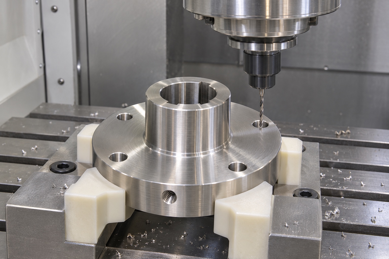
Plan turning and secondary operations together
Turning can establish accessible bore, boss and flange features as a coherent reference set when the actual setup supports that relationship. Review how the hub is held for the keyway, flange pattern and radial hole afterward. Workholding should recover finished references without marking them or covering necessary access. Sequence and cutting conditions depend on the blank, machine and geometry; no universal speed or feed is proposed. The process plan should identify which surfaces are finished together, which are transferred and which will be inspected after subsequent cutting. One setup can reduce transfers, but it is not evidence that every relationship is automatically correct.
Control edges at intersecting features
The bore entrance, keyway edges, flange holes and radial thread can retain raised material or chips. Define permitted edge finishing without removing a useful locating surface or changing a keyway contact face. Where the radial hole intersects the bore, inspect the actual intersection using an agreed method. A smooth outer mouth does not establish the condition inside. Do not use an inserted shaft to push unexplained debris aside and call the fit acceptable. Cleaning and dimensional checks should remain identifiable steps. Ordinary removal of machining chips must not be described as sterile preparation or approval for contact with reagents or patient samples.
Build a relationship-based inspection plan
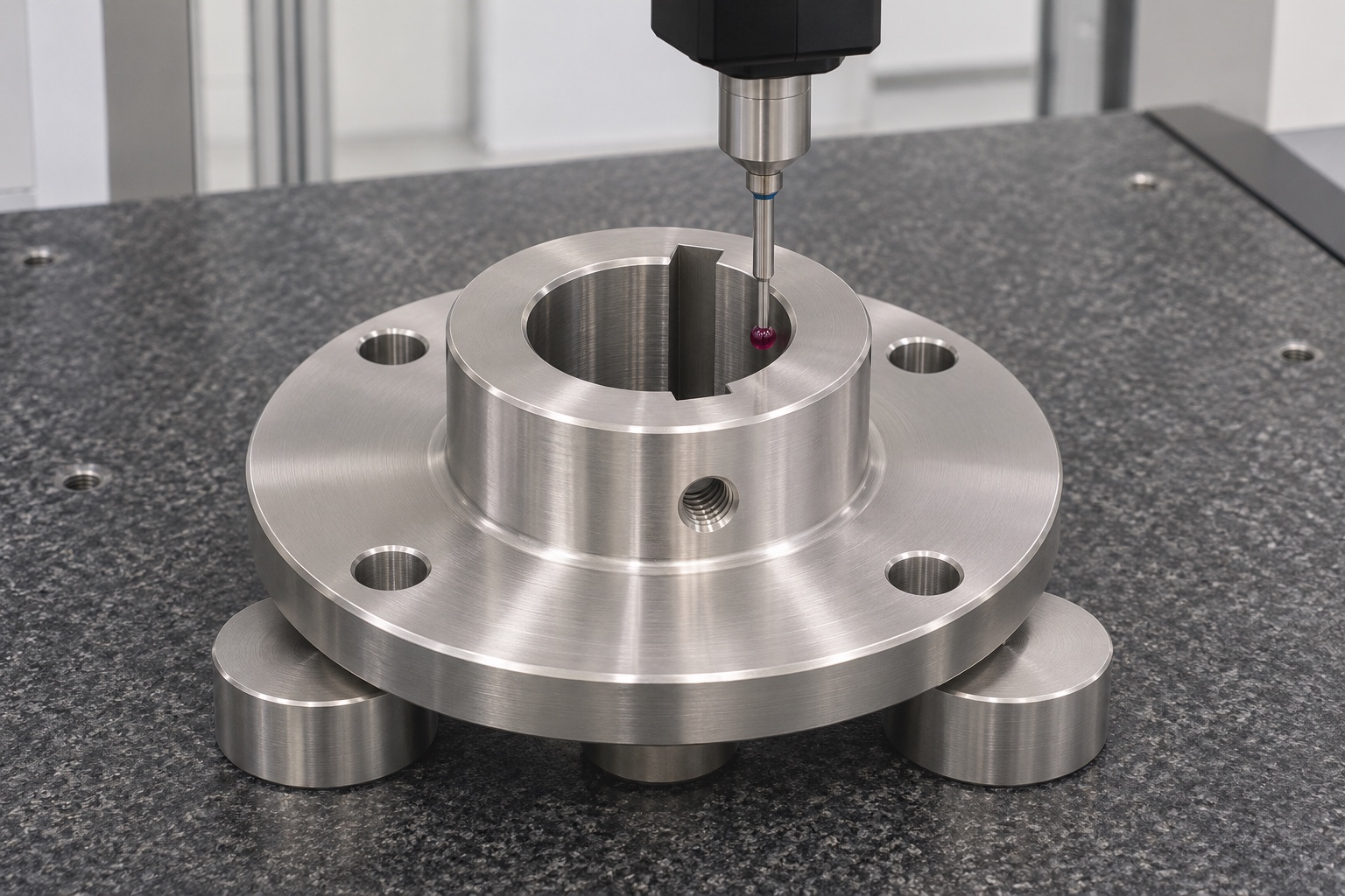
Evaluate the locating bore, axial face, keyway and flange pattern in the specified datum system. A diameter check cannot establish keyway clocking or face orientation. Choose measurement methods based on access and the characteristic, including how a keyway depth is referenced to the bore. A coordinate setup needs defined contacts just as any other method does. Record drawing revision, final surface state and which features were checked. This article offers no invented tolerances or measured results. Real acceptance values must come from approved requirements and actual inspection evidence associated with identified parts, not from the generic appearance of a precision hub.
Limit a dry fit to its geometric purpose
An identified inert shaft and key reference can help locate interference without operating a carousel or using reagents. Record insertion direction, support and the point at which contact occurs. Do not force the reference past an unexplained obstruction. The observation may show a local fit condition, but it cannot establish dynamic balance, transmitted torque, indexing accuracy or assay reliability. Those outcomes require separate approved conditions and evidence. A useful bench note distinguishes contact at the bore, keyway, flange face or fastener envelope. That distinction is more informative than reporting that the assembly simply feels tight or loose.
Diagnose mismatch before altering the interface
If a reference shaft stops early, inspect bore entry, keyway end, raised edges, reference identity and alignment before changing dimensions. If flange holes do not align, confirm pattern origin and keyway clocking rather than enlarging all holes. Corrections need an approved disposition and repeat inspection of affected characteristics. Preserve the original observation so the cause is not lost during hand finishing. Separate a manufacturing deviation from an incomplete assembly definition. Both can produce the same first symptom, but they require different decisions. A reproducible approved interface is the goal, not an isolated fit achieved by undocumented material removal.
Protect the hub and prepare a complete request
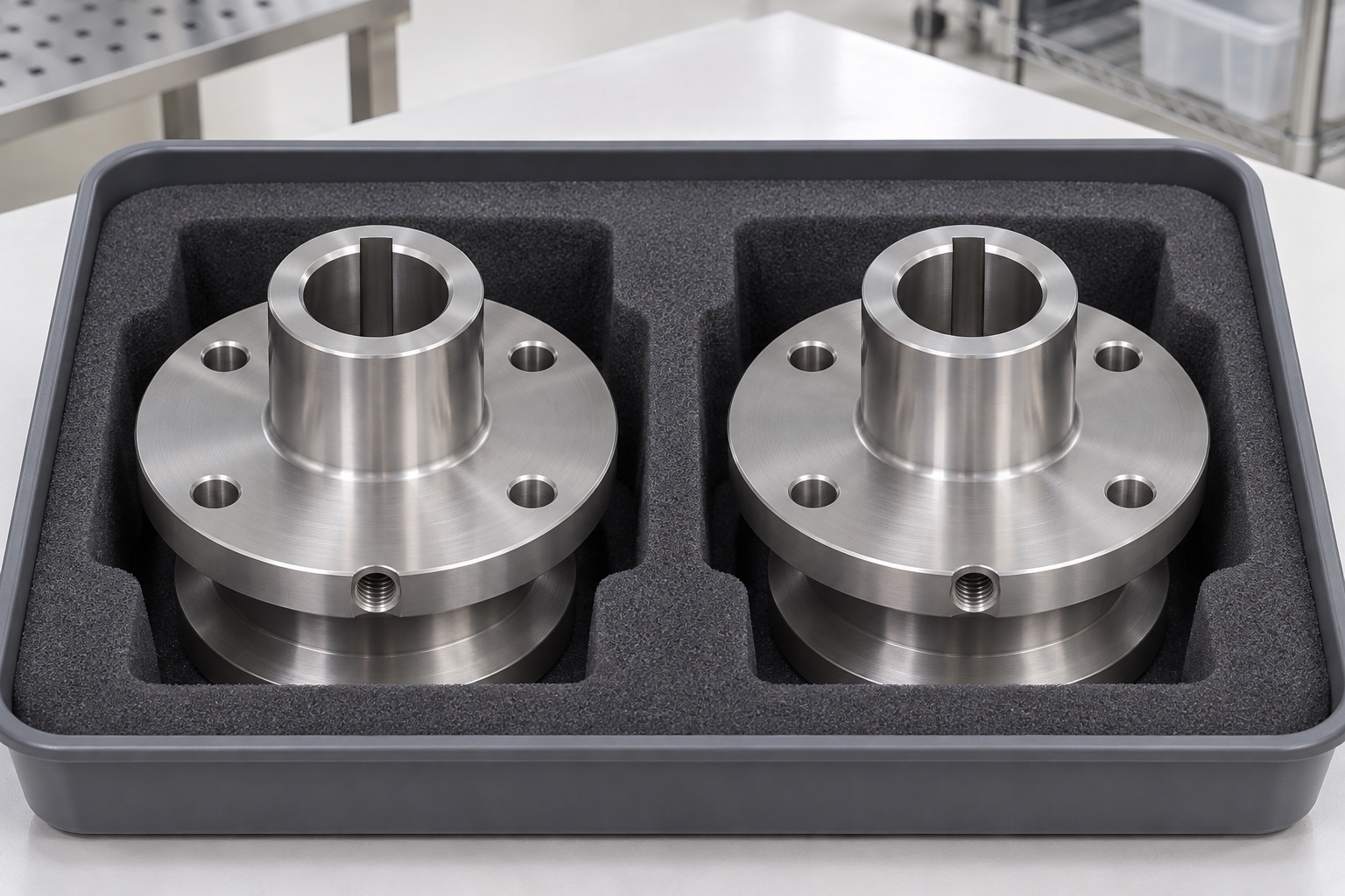
Package hubs separately so flange faces, bore entries and boss surfaces cannot strike another metal component. Avoid protective contacts that leave debris in the keyway or thread. Maintain revision and material identity with the inspection record; ordinary packaging does not establish sterile delivery. A machining request should include controlled drawing and model, material, quantity, final surface state, datum scheme, keyway details, flange pattern and thread requirements. Add the approved mating geometry where it determines clearance. Resolve first-article reporting and packaging expectations before production. This gives a stainless steel machining supplier a verifiable scope without inventing approval for the complete medical analyzer.
FAQ
Does a correct bore size prove flange alignment?
No. Bore size, axial face orientation and flange-pattern position are different characteristics. Inspect their specified relationships using the approved datum system rather than relying on a diameter reading alone.
Does the nominal key size fully define the keyway?
No. Width, depth definition, useful length, end condition and angular relationship need separate description. The mating key and shaft also need identified geometry where they govern clearance.
Can the radial thread be accepted only with a screw trial?
No. Define thread identity, engagement and position, then use the approved inspection method. A screw trial does not establish retention force, screw-tip behavior or permissible torque for the assembly.
Does an inert shaft fit qualify carousel operation?
No. It provides a limited geometric observation. It does not demonstrate balance, indexing performance, operating speed, reagent handling or analytical accuracy of the complete instrument.
What should happen before enlarging misaligned flange holes?
Check pattern origin, bore reference, keyway clocking and the mating reference first. Any correction must be authorized and followed by inspection of affected characteristics; do not conceal an unidentified cause.
Which files help a supplier quote this hub?
Provide matching drawing and model revisions, material and surface requirements, quantity, reference scheme, keyway and thread details, inspection scope and packaging requirements, plus approved mating geometry when needed.

tanghangyun@oemach.com