
A high encoder resolution does not remove mechanical mounting error. If the scale center is eccentric to the true rotation axis, or its face wobbles, the measurement error can repeat around every revolution.
The mount should be machined and inspected from the actual bearing axis, with radial eccentricity, axial runout and readhead gap measured separately and compared with the full-revolution angle-error curve.
Encoder mounting risks
| Risk | Cause | Control |
|---|---|---|
| Angle error repeats once per revolution | Scale center is eccentric | Control the common axis and record eccentricity direction |
| Repeatability varies with angle | Face runout changes readhead gap | Control perpendicularity and axial runout |
| Error rises after replacement | Datum, tightening or calibration changed | Standardize assembly and re-establish the baseline |
Understand periodic error from eccentricity
The scale or code-disc center moving around the rotation axis changes the readhead geometry with angle. Nominal resolution describes increment size, not immunity to this systematic mechanical error.
Control face wobble and readhead gap
A nonperpendicular mounting face causes periodic gap change that can affect optical, magnetic or capacitive signal quality. Separate the radial locating surface, axial face and readhead mounting feature on the drawing.
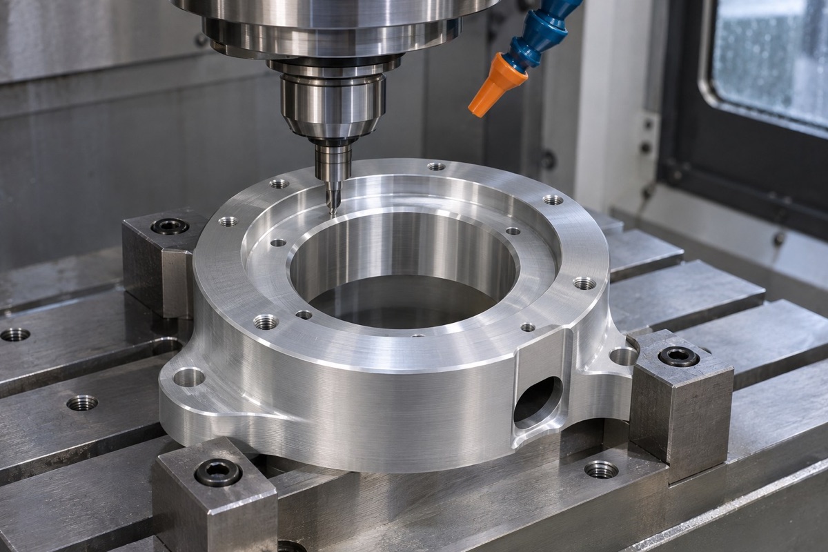
Radial locating and axial mounting surfaces should be produced from the actual bearing-axis datum.
Use the real rotation axis as the machining datum
Where possible, finish encoder locating and face features from the same datum used for bearing bores or establish a verified transfer. An external housing surface is not sufficient unless its relationship to the bearing axis is proven.
Make assembly adjustment repeatable
Adjustment screws or readhead motion can reduce one installation's error, but the pilot, fastener clearance, tightening sequence and cable force must remain controlled. Correct mount form before relying on adjustment.
Connect mechanical and angular measurements
Measure radial and axial runout under the same support and temperature used for the angle reference test. Compare phase and waveform to distinguish eccentricity, bearing error motion and scale error, and rebaseline after repair or replacement.
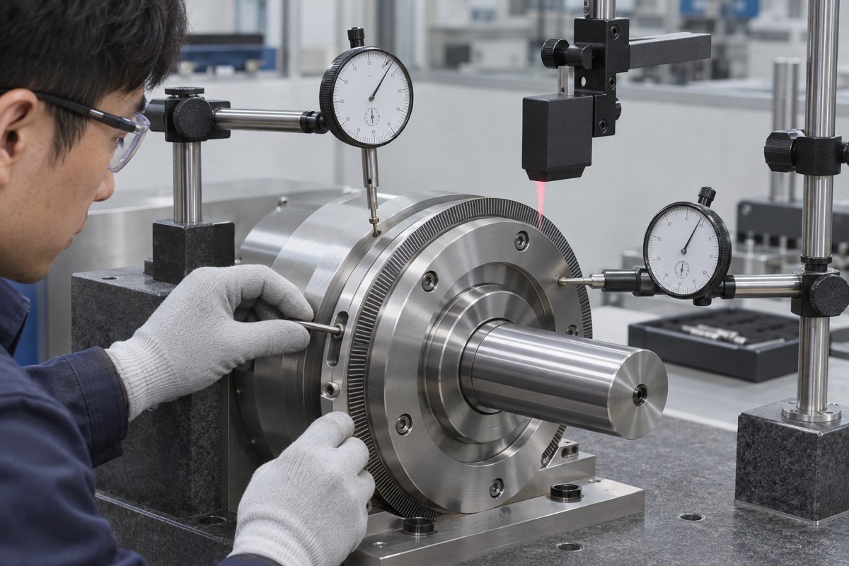
Relating runout direction to the full-revolution error curve helps separate mounting, bearing and encoder errors.
Summary
Encoder accuracy requires the mount to follow the true rotation axis. Radial eccentricity, face runout, readhead gap, assembly procedure and the full angle-error curve must be evaluated together.
FAQ
Does high encoder resolution make eccentricity unimportant?
No. Resolution is the smallest readable increment; eccentricity still creates systematic measurement error.
Are coaxiality and radial runout identical?
No. Runout is a practical rotational measurement that can also contain roundness and datum errors.
Can software compensation replace mechanical control?
Only for stable repeatable error. It cannot replace a mounting condition that changes with removal, temperature or load.
Ready to get a quote for your CNC machined parts?
Submit your engineering drawings to qiancj@oemach.com. We support prototype sampling and small-batch production with strict tolerance control.