
Calibration fits a coordinate relationship for the current mechanical state; it cannot prevent that state from changing after vibration, temperature change or camera removal.
The bracket's functional datums must represent the optical axis and robot coordinate system, while stiffness, thermal behavior and installation repeatability are validated with calibration data.
Calibration drift risks
| Risk | Cause | Control |
|---|---|---|
| Coordinates drift after calibration | Low stiffness, heat or interface movement | Control load path and compare hot/cold calibration |
| Large change after camera removal | Mounting face and locators do not restore pose | Add repeatable location and verify reinstallations |
| Bracket dimensions pass but optical axis tilts | Inspection datum does not match optical coordinates | Include optical mounting features in one datum chain |
Recognize how bracket error enters calibration
Mount-face angle, locator offset and bracket deflection change camera extrinsics. Software can fit the current state but cannot make a moving bracket mechanically stable.
Make drawing datums represent optical relationships
Relate the camera face and locators to the robot-side connection and intended optical direction. Convenient outer stock surfaces should not replace a measurable functional datum chain.
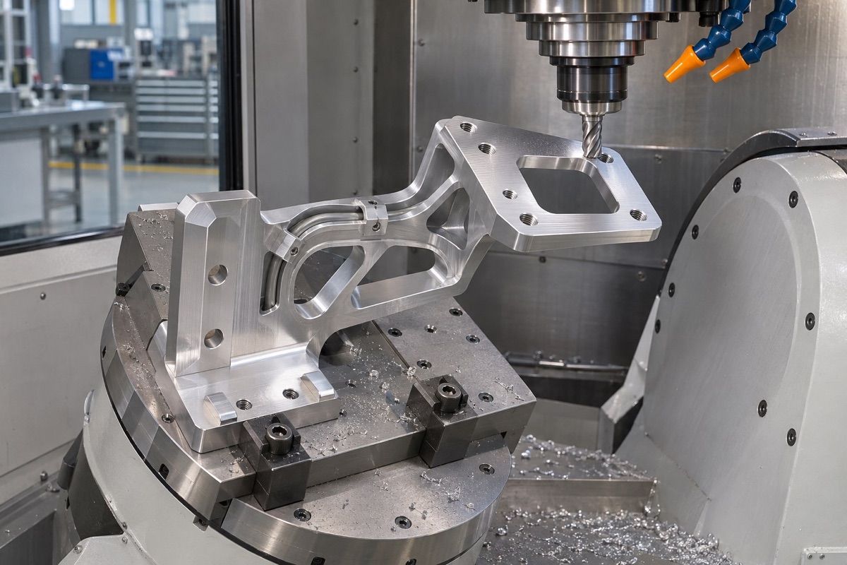
Camera mounting faces and locating features should be finished from a stable robot-side reference.
Plan machining for a lightweight structure
Thin walls, windows and cantilevers can release stress after heavy stock removal. Rough first, establish a stable connection datum, then finish the camera face and locators with minimal datum changes.
Validate stiffness and temperature beyond static dimensions
Camera mass, cable force, robot acceleration and nearby heat sources can move the optical pose. Combine static metrology with vibration or temperature-cycle calibration checks.
Verify removal and calibration traceability
Use pilots, dowels or precision faces without overconstraint and repeat camera removal and installation. Link bracket ID, machining report, assembly condition and residual calibration error.
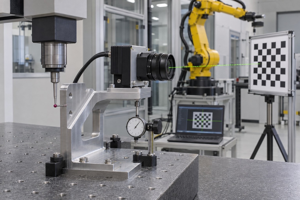
Bracket ID, installation state, temperature and calibration data should remain traceable.
Summary
Stable robot vision requires a bracket whose datums match the optical coordinate relationship, whose structure resists load and temperature changes, and whose installation repeatability is proven with calibration data.
FAQ
Does a dimensionally conforming bracket guarantee accurate calibration?
No. Datum definition, stiffness, installation, temperature and the calibration method also matter.
Is a thicker camera bracket always more stable?
No. Stiffness depends on structure and load path; added mass can worsen robot dynamics.
Must calibration be repeated after changing the camera?
Usually it must be evaluated because camera, lens or mounting changes can alter intrinsic or extrinsic parameters.
Ready to get a quote for your CNC machined parts?
Submit your engineering drawings to qiancj@oemach.com. We support prototype sampling and small-batch production with strict tolerance control.