
A standardized circular interface improves tool interchangeability, but the standard alone does not guarantee repeated tool-center position. Manufacturing and assembly conditions still control the result.
Confirm the applicable interface size and load boundary, then treat the face, pilot and oriented hole pattern as one datum system and validate it through repeated installation cycles.
Repeatability risks
| Risk | Cause | Control |
|---|---|---|
| Tool mounts in more than one orientation | Pattern or orientation feature is unclear | Confirm interface edition, direction and markings |
| TCP shifts after reinstallation | Pilot clearance, debris or tightening variation | Control contact surfaces and repeat the defined cycle |
| Holes pass but face runout is high | Pattern and face use different datums | Finish face, pilot and pattern together |
Confirm what the standard interface covers
ISO 9409-1 defines key dimensions and orientation for circular robot interfaces, but does not replace the robot's load limits, manufacturing tolerances or system validation. Confirm flange size, payload, tool center of gravity and released drawing.
Use face and center pilot together
The face establishes axial location while the pilot restores radial center. Their flatness, perpendicularity, form and relationship to the rotation axis should be produced from a common datum.
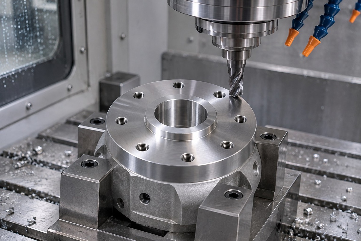
Face, center pilot and oriented hole pattern should be finished as one functional interface.
Control the oriented hole pattern
Threaded or clearance holes need correct position relative to the face and pilot. If the pattern defines angular orientation, the datum direction must be explicit; bolt clearance should not become an alignment method.
Standardize surface condition and tightening
Chips, coating buildup, dents and burrs alter contact. Define masking or post-treatment areas, cleaning, fastener condition and cross-tightening sequence for every installation.
Validate through repeated installation
Remove, clean, reinstall and tighten the same tool plate several times under one procedure. Record face runout, reference-sphere or TCP position and separate robot repeatability, interface repeatability and measurement error.
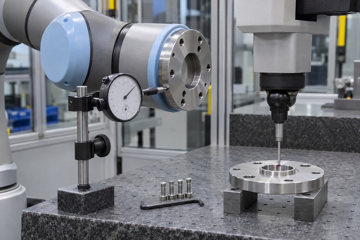
Multiple remove-clean-install-tighten cycles separate interface repeatability from one static measurement.
Summary
A standard hole pattern is only the starting point. Reliable cobot tool reinstallation requires one face-pilot-pattern datum system, controlled surfaces and tightening, and repeated cycle evidence.
FAQ
Does an ISO pattern guarantee every tool is interchangeable?
No. The exact interface size, load, pilot fit, tool-plate design and fastening conditions must also match.
Is interface repeatability the same as robot positioning repeatability?
No. One concerns restoration after disassembly; the other concerns robot motion performance.
Can the face be used directly after coating?
Only if the coating thickness and uniformity meet the design; masking or post-machining may be required.
Ready to get a quote for your CNC machined parts?
Submit your engineering drawings to qiancj@oemach.com. We support prototype sampling and small-batch production with strict tolerance control.