
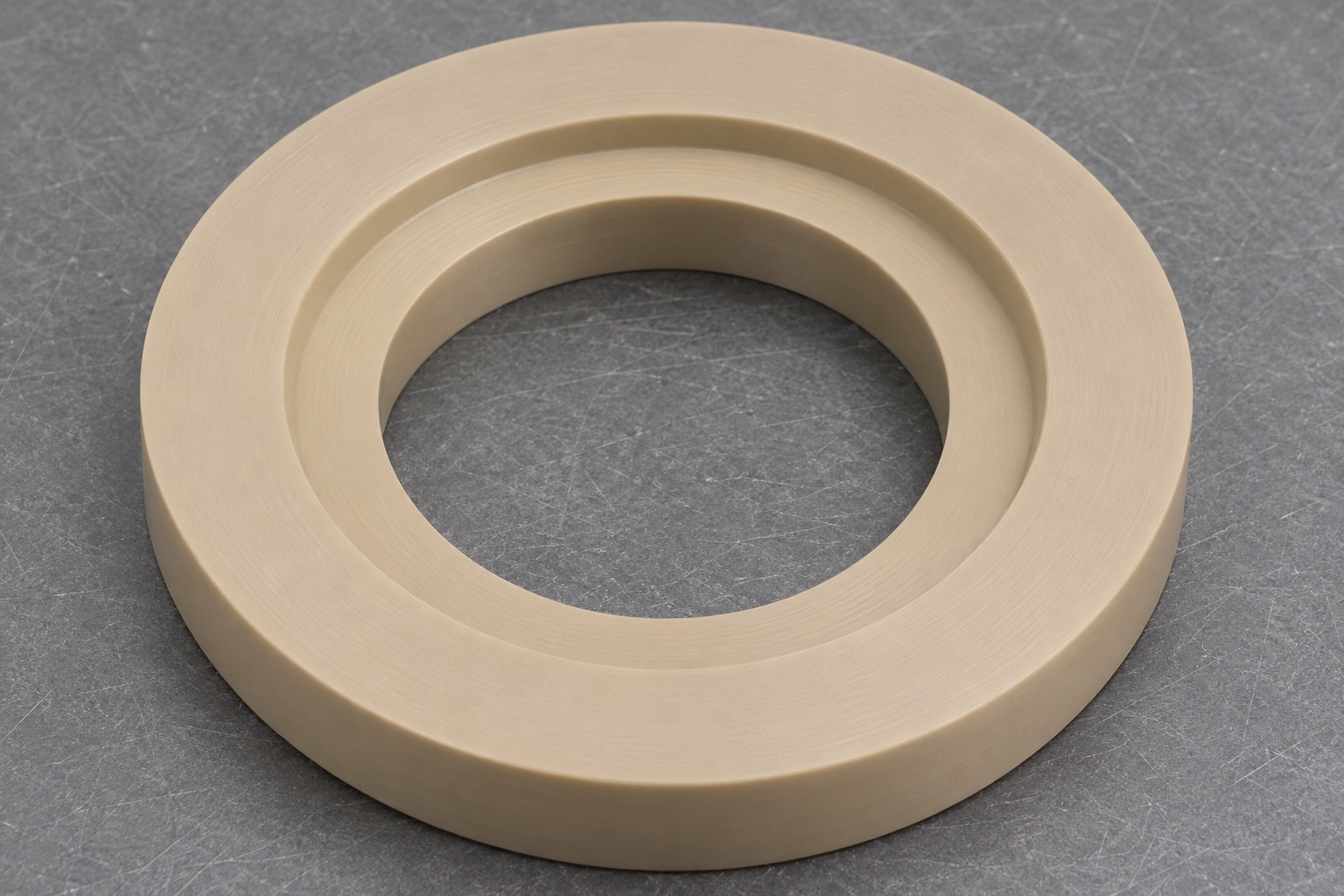
Identify the support function and its limits
PEEK CNC turning of a medical suction pump diaphragm backing ring concerns a separately specified mechanical support component. The ring may provide an annular seat, a central opening and a stepped face for a defined assembly. This guide addresses manufacturing and geometric inspection, not the design of a working pump or instructions for servicing clinical equipment. A correctly machined ring does not establish suction performance, diaphragm life, leak resistance or safe use. The owner must supply the actual interface and acceptance requirements. Keep material identity, dimensional acceptance and qualification of the complete pump as distinct forms of evidence rather than treating one as proof of the others.

Define which annular surfaces carry the reference
Identify the face that locates the ring and the regions intended to support the separate diaphragm or reference component. A broad visible face is not automatically a functional seat over its entire area. Show steps, lands and clearances explicitly. Relate the center opening and any external locating diameter to the actual reference structure. A nominally centered hole does not define the required relationship by itself. The inspector needs to reproduce the drawing's reference without pressing the ring against an arbitrary fixture until it appears flat. Distinguish free-state requirements from any mounted condition that the owner has deliberately specified for acceptance.
Specify the PEEK grade and stock condition
Identify the exact PEEK grade, whether it is filled or unfilled, the stock form and required documents. Similar color does not establish equivalent material. A change in reinforcement or processing history can introduce different machining and application requirements. If exposure, cleaning or contact requirements apply, obtain them from the approved design rather than inferring them from the polymer family. This guide does not qualify a stock shape for a medical application. The purchase package should also identify any approved conditioning process and the point at which final dimensions are measured. Do not invent a universal heat-treatment schedule for all rings.
Review the step, wall and corner geometry together
An annular step can leave a narrow lip or thin region that needs support during cutting and measurement. Review the useful width, remaining wall and tool access together. Internal radii should be practical for the selected route and should not be silently altered to suit an available tool. If a nearby edge must remain limited, identify it on the drawing. A corner radius, an entry chamfer and a supporting land have different functions. The supplier should know which geometry must be preserved and which clearance can be discussed. Resolving these details before quotation is more useful than assigning equally tight requirements to every surface.
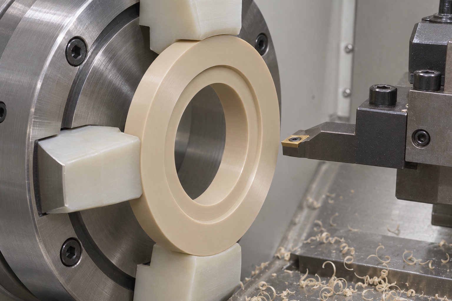
Plan material removal while retaining support
The roughing route should remove material without releasing an unsupported final ring too early. Identify which features remain available for locating and how the component is held during the last operation. A thick blank and a thin annular part can respond differently to the same clamping force. Review cutting heat, stock history and the inspection condition when deciding the finish sequence. Any proposed conditioning step must be appropriate to the actual grade and approved route. The process should not accept a warm or heavily constrained measurement as the finished free-state result. Record the planned sequence instead of assuming polymer dimensions are independent of the manufacturing condition.
Choose workholding that does not manufacture a false shape
Support the ring at defined robust regions and control the contact used to locate it. A collet, soft jaws or a dedicated fixture may be considered according to the actual geometry. The choice alone does not prove that distortion is absent. Verify the required geometry after release or in the defined mounted state. Avoid clamping across a thin lip merely because it is easy to reach. The setup sheet should show the support and the measurement plan should identify any difference from that setup. This makes it possible to distinguish component geometry from a shape created temporarily by the holder.
Finish faces and bore with a clear relationship
Decide which face, bore and exterior features should be finished while maintaining a common reference. If the ring is reversed, define how that reference is recovered without damaging the completed land. Check the useful bore length separately from its entry and relief. A correct diameter does not establish the opening's position relative to the supporting region. The axial step and face relationship also need their own defined measurements. No achieved flatness, parallelism or tolerance capability is asserted here. The route must be reviewed against the actual drawing and the supplier's proposed evidence rather than an unqualified statement about precision PEEK machining.
Control edge finishing near the support land
A local edge detail should remove prohibited raised or smeared material without reducing the useful support width. The drawing should distinguish a deliberate relief from a defect. Do not hand-smooth the entire ring until it looks uniform if doing so changes a functional face or step. Inspect affected geometry after the finishing operation. If a thin region deflects under the proposed tool or measurement, review support and method rather than accepting the appearance alone. A dry assembly that seems to seat cannot independently confirm all local edges. Each acceptance characteristic needs a suitable method and an identifiable point in the process.
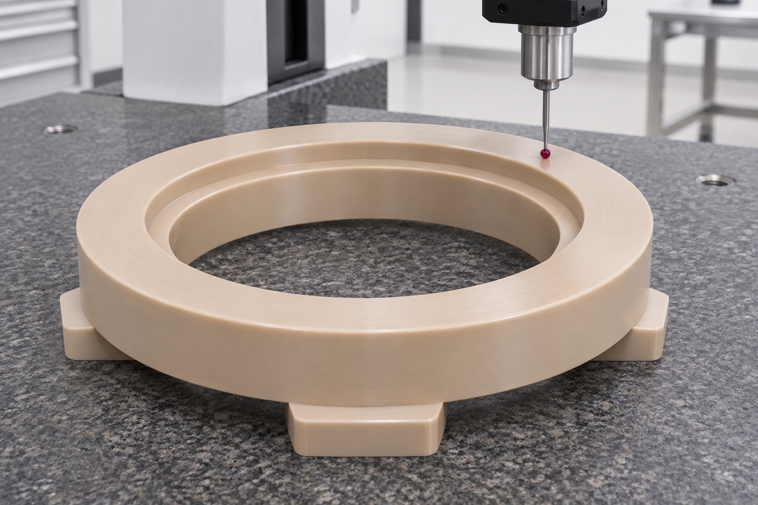
Inspect the ring under a documented condition
The inspection plan should identify the support face, step, central opening and required relationships. Allow the part and instruments to reach the specified measurement condition. Choose contact force and support that do not distort the characteristic being measured; appropriate optical or low-force methods may be useful, depending on the drawing. Evaluate defined annular regions instead of taking one convenient thickness measurement and accepting every face. Record whether the component is free or mounted, along with the actual references. A report that identifies the measured regions and conditions is more reproducible than an unsupported statement that the ring is flat and concentric.
Separate geometric seating from pump qualification
A controlled bench arrangement can use an identified inert reference to observe seating and clearance without a working diaphragm, vacuum source or clinical pump. Record support, orientation and contact locations. Such an observation may help identify an unintended high point, but it does not establish leakage, pressure behavior, service life or compatibility with the actual diaphragm. Those questions require separate approved evaluation of the relevant assembly. Do not use an operating medical suction device for an improvised component trial. Keep the limited geometric observation associated with its own conditions and compare it with the dimensional results rather than treating a stable seat as broad functional approval.
Investigate changes before approving rework
If the ring appears to rock or the inert reference does not seat, check the reference, local edges, support arrangement and measured face geometry. Preserve the observation before removing material. Lowering the whole land or opening the bore can change the intended interface while concealing the original cause. A correction needs an approved disposition and repeat checks of affected features. Record any change in the fixture or reference as well. Reinspection should evaluate the same requirement under known conditions, not compare two different setups as though only the part changed. Distinguish a support problem, a local burr and an incorrect machined face.
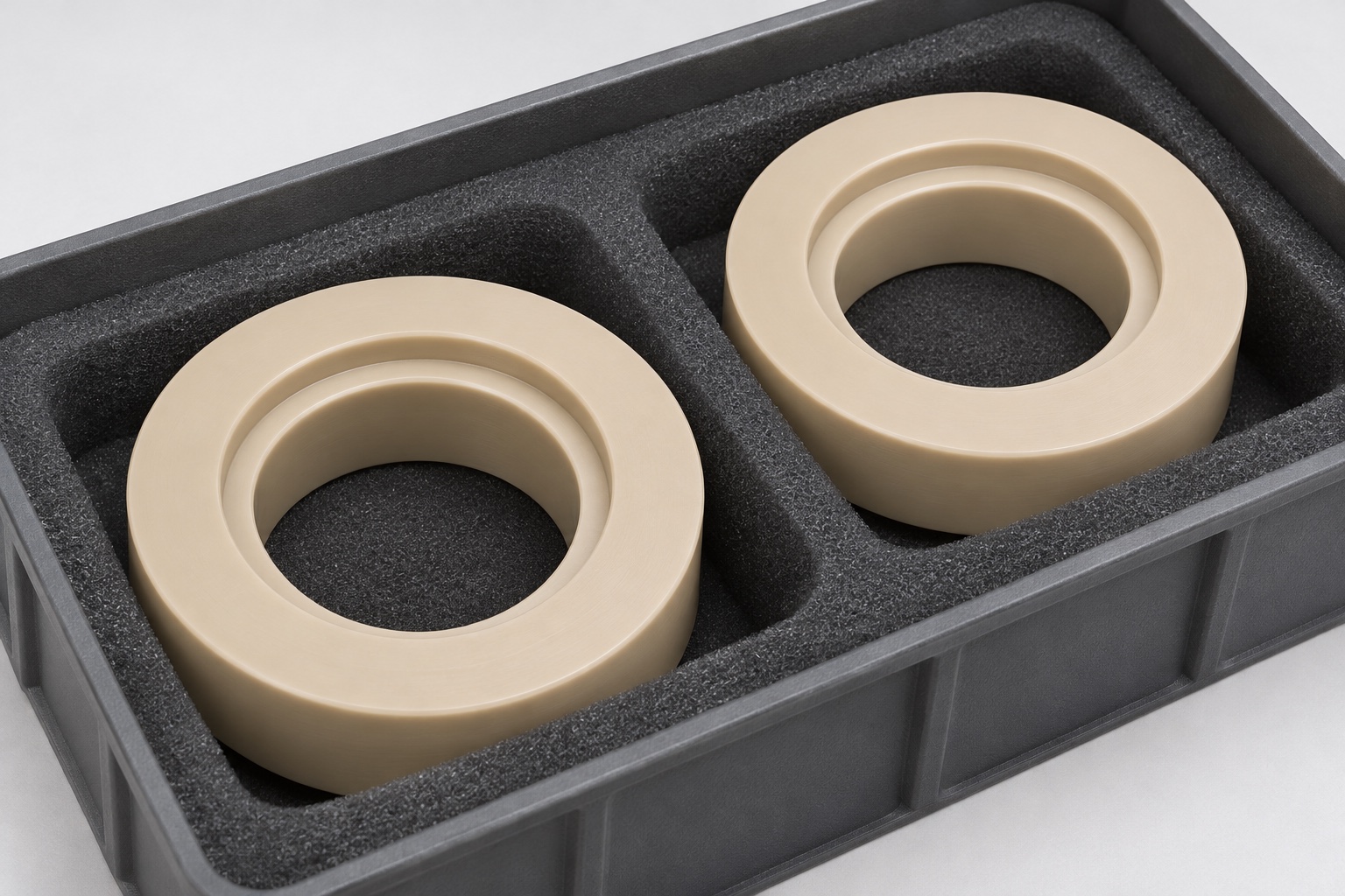
Protect the ring and define the manufacturing request
Package rings separately with support that does not preload thin sections or push unapproved material into the opening. Keep material and revision identity connected to the inspection records. Ordinary transport protection does not establish sterility or a specified cleanliness level. A useful request includes the controlled drawing, PEEK grade, quantity, reference scheme, face and bore requirements, final condition and required evidence. Identify any mounted-state inspection or approved conditioning step explicitly. Review access and first-article findings before releasing a batch. This makes component acceptance verifiable without inventing pump performance, exposure compatibility or approval for the complete clinical suction system.
FAQ
Does the PEEK name qualify the component for suction equipment?
No. Grade, stock, interface and application requirements must be specified and supported by the appropriate evidence. The material family is not a device approval.
Can a ring be measured only while tightly clamped?
Only if that is the required defined condition. Do not present a constrained shape as free-state geometry without the corresponding inspection plan.
Does bore size establish its position to the seat?
No. Diameter and the geometric relationship to the support region are distinct characteristics that need their own defined evaluation.
Is a universal conditioning schedule appropriate?
No. Any conditioning or stress-relief step must follow an approved procedure suited to the material and component, with dimensions checked at the required stage.
Does an inert seating trial establish leak resistance?
No. It observes geometry in one bench setup. Pump performance, diaphragm behavior and leakage require separate controlled evidence.
What should be reviewed before lowering a supporting face?
Check reference identity, edges, support and measurements. Obtain approval for any correction and repeat every affected dimensional check.

tanghangyun@oemach.com