
Separate the holder from the calibration artifact
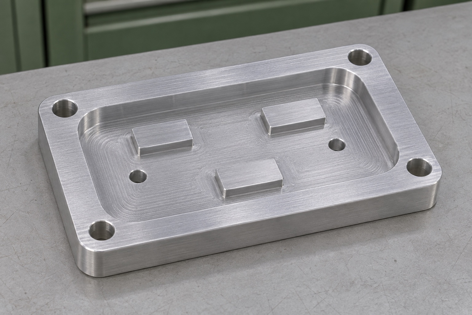
6061 CNC milling for an intraoral scanner target carrier addresses the geometry that holds a separate reference object in a dental equipment engineering fixture. The carrier can have a mounting base, seating lands and locating features. Those features do not make the carrier a calibrated artifact or establish scanner accuracy. This guide discusses a generic holder as a machined component, not a procedure for calibrating a clinical instrument. The responsible owner must define the target, its interface and any system-level acceptance requirements. Start by distinguishing the surfaces the machining supplier will produce from the optical information and approval evidence supplied elsewhere.

Define the mounting datum and target reference
Identify how the carrier locates in its supporting fixture, then define the target's seating plane and position relative to that mounting reference. A flat pocket floor does not automatically represent the intended target plane if only raised lands support the object. Make the actual contacts explicit. Distinguish the features that locate the target from fasteners or clamps that merely retain it. The inspector needs to reproduce the drawing's reference structure without guessing which nearby face is functional. If more than one target type is contemplated, their interfaces need controlled definitions rather than a general statement that the same pocket accepts them all.
Specify seating lands and clearance regions
Show which portions of the carrier support the reference object and which regions provide clearance. Do not require the entire pocket to meet the same plane requirement if only specified lands are functional. Conversely, do not assume unmeasured pocket regions are harmless when they could contact the target. Include appropriate reliefs and accessible internal radii in the design review. A small burr or local raised area may create an unintended contact even when the main machined surfaces appear correct. The drawing and inspection plan should make it possible to tell a deliberate support point from accidental interference before assembly is attempted.
Identify 6061 stock and the finished surface state
Specify alloy, temper, stock form and required documentation. If an anodized or other treated finish is required, state whether the seating and locating requirements apply before or after treatment. Identify protected contacts or masking requirements where they matter. Do not select a finish solely because its color seems suitable for an optical fixture. The surface's optical behavior, durability and compatibility need the application's actual requirements. This guide makes no claim that a finish improves scanner performance. The supplier needs a verifiable final condition and a route that checks critical geometry after any process capable of changing it.
Plan roughing with support and allowance
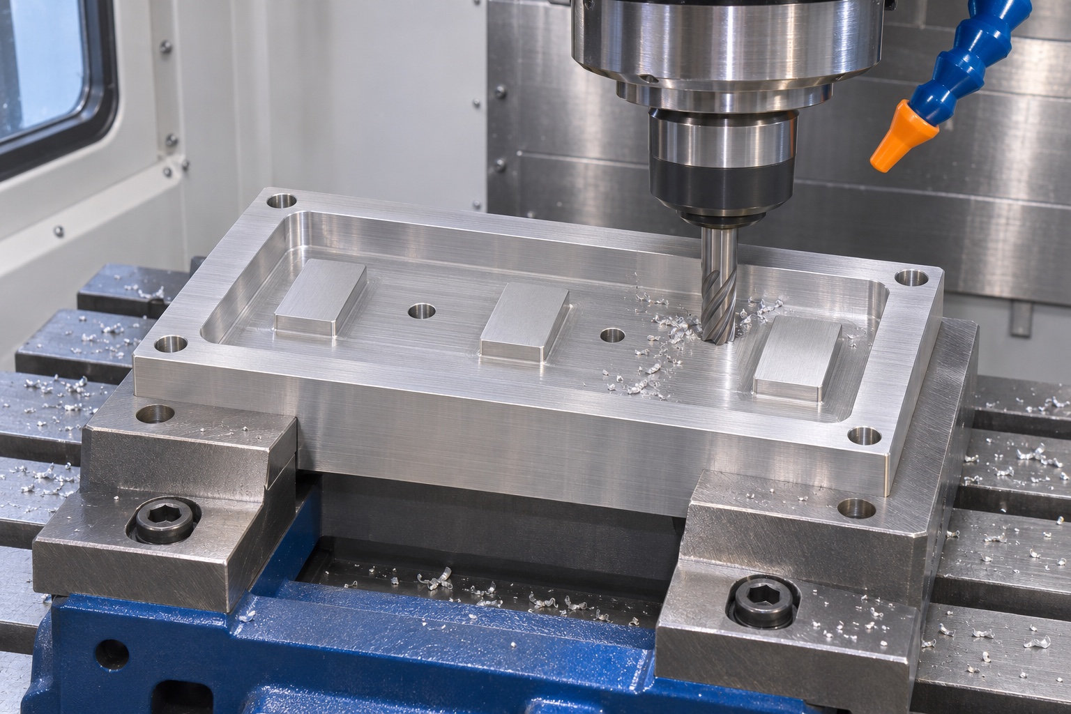
Review the blank, mounting region and pocket layout before removing material. Preserve useful locating surfaces for the operations that establish the target plane and locator positions. A deep pocket or narrow remaining land can change the part's response to clamping compared with the original block. The setup should show where the carrier rests and where force is applied. Leave an appropriate finish allowance for the actual route rather than treating every surface as complete during roughing. The plan should also consider inspection access and how the part will be measured after release, so the accepted geometry is not merely the shape created by the fixture.
Preserve the relation between plane and locating features
Where practical, finish the related seating lands and locating features while maintaining a common reference. This can reduce transfers, but it does not prove the result by itself. If another setup is needed, define how the mounting datum is recovered and checked. Review cutter access near pocket walls and locator details before assigning a route. A measured hole diameter does not independently establish its position relative to the seating plane. The process sheet should identify which geometric relationships are being preserved rather than describing the work only as machining a pocket and drilling holes.
Finish edges without creating new contact points
Edge treatment around seating lands, reliefs and locating holes must preserve their useful geometry. A burr at a hole mouth or an oversized hand-finished chamfer can alter how a separate locator or target sits. Define the allowed condition on the drawing and inspect after the operation that creates it. Do not smooth a functional land by hand merely to make the part look uniform. If a local finish requirement cannot be measured with the proposed equipment, resolve that before accepting it. Appearance, roughness and geometric plane requirements are different characteristics and should not be merged into one instruction to make the carrier precise.
Inspect seating geometry in a reproducible setup
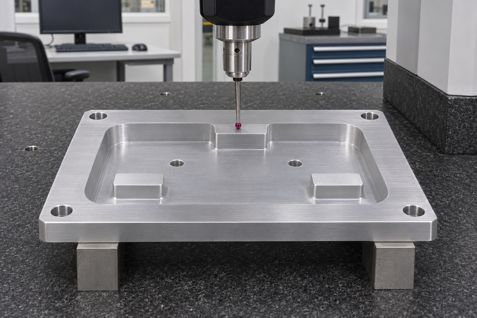
The inspection plan should identify the mounting references, the land regions evaluated and the method used to establish the target plane. Record the part's support condition and whether the requirement applies in a free or defined mounted state. Suitable coordinate or other dimensional methods depend on actual access and the drawing characteristic. Avoid fitting a convenient plane through points that ignore a required land or include a noncontact clearance region. If the carrier rocks, investigate debris, edges, support and part geometry before interpreting another result. A clear report identifies what was measured rather than relying on an unqualified statement that the pocket is flat.
Check locators and installed reference height separately
Measure locator positions and the relevant interface features against the approved datum scheme. A pin fitting into a hole does not prove where the hole is located or what height a target will occupy. If separate locators are installed, the drawing and order must define their identity, installation condition and any final assembly inspection. Do not infer a press fit or install hardware based only on a picture. The carrier's component measurements and the mounted reference object's observed position are related but distinct records. Keeping them separate helps determine whether a discrepancy belongs to machining, a locator or the reference object.
Use an inert seating trial for geometry only
A controlled bench arrangement can use a defined inert blank to observe seating and clearance without performing optical calibration. Identify the blank, support and observation method. Do not use a scanner's apparent response as a substitute for dimensional inspection or modify an operating clinical setup to evaluate a generic holder. A blank that seats without rocking does not establish optical accuracy, repeatability across sessions or compatibility with a commercial scanner. The meaningful output is a limited geometric observation under specified conditions, compared with the measured carrier features and the actual interface requirements. Broader claims need their own approved evidence.
Investigate a seating discrepancy before rework
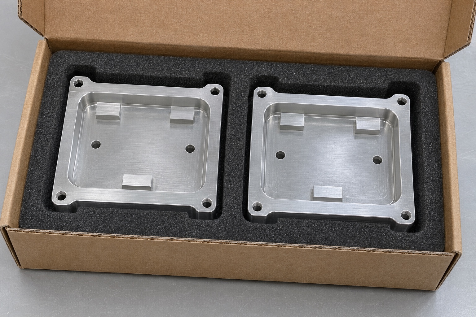
If an inert reference contacts an unintended surface, preserve the observation and inspect the relevant land, relief, local edge and locator condition. Check the reference object and fixture before changing the carrier. Lowering every land or enlarging a pocket may remove visible contact while changing the target plane the design intended to hold. Any correction must follow an approved disposition and repeat inspection of affected characteristics. After acceptance, protect the seating regions from impacts and residue. Packing materials should not preload thin features or leave an uncontrolled film on a functional contact, and ordinary packaging should not be described as sterile delivery.
Prepare an evidence-based machining request
Provide the controlled model and drawing, 6061 material condition, quantity, finish state, datum scheme, critical seating and locator requirements, and inspection deliverables. Identify the separate target or locator interface without asking the machining supplier to infer calibration requirements from the word scanner. Discuss tool and measuring access before placing the order. For a first article, agree how discrepancies and proposed design changes will be reviewed before a batch proceeds. This creates a useful component acceptance plan without inventing optical performance or clinical compatibility. The holder's geometric evidence remains distinct from the calibration artifact and the approval of the complete dental scanning system.
FAQ
Is the target carrier itself a calibrated artifact?
No. The machined holder supports a separately defined reference object. Its dimensions alone do not establish optical calibration or scanner accuracy.
Why distinguish seating lands from the pocket floor?
Only the defined contact regions establish the intended seat. Clearance regions should not be mistaken for measured support surfaces, or allowed to create unintended contact.
Does a pin fitting prove its position?
No. Fit checks a local interface condition. Locator position and its relation to the mounting and seating references need separate dimensional evidence.
Should the seating plane be checked after treatment?
Inspect in the final state required by the drawing. Any treatment or installation step that can affect critical geometry needs an appropriate verification plan.
Can an inert blank qualify an intraoral scanner?
No. A bench seating observation is limited to geometry under that setup. Optical accuracy and system approval require separate controlled evidence.
What should be reviewed before lowering a high seating land?
Confirm the reference, support, local edges and measured geometry. Obtain approval for a correction and recheck every affected plane or locating relationship.

tanghangyun@oemach.com