
A robot drive shaft can pass every individual diameter check and still run poorly if its journals, spline and keyway do not share the intended rotation axis. Rotational accuracy must be planned as a chain, not inspected as isolated dimensions.
The process should preserve a common center reference, anticipate heat-treatment movement and reserve appropriate stock for finishing. Exact tolerances and process choices remain drawing-specific.
Common shaft problems and controls
| Problem | Main cause | Control |
|---|---|---|
| Journal and spline are not coaxial | Different references between operations | Maintain protected centers or another verified common axis |
| Spline gauges pass but assembly is tight | Profile, lead, burr or mating-axis error | Inspect tooth geometry and functional relationship, not only GO/NO-GO |
| Shaft bends after heat treatment | Residual stress, loading or nonuniform transformation | Measure pre/post heat treatment and plan finish allowance |
Build the route around one rotation axis
Center holes or an equivalent precision datum should survive every relevant operation. Their protection and reconditioning rules need to be documented because a damaged center can transfer error to every finish-ground journal.
Select the spline process by function
Hobbing, shaping, broaching, milling and grinding provide different access, volume and accuracy capabilities. Selection should consider tooth form, heat-treatment state and how profile, lead and axis relationship will be verified.
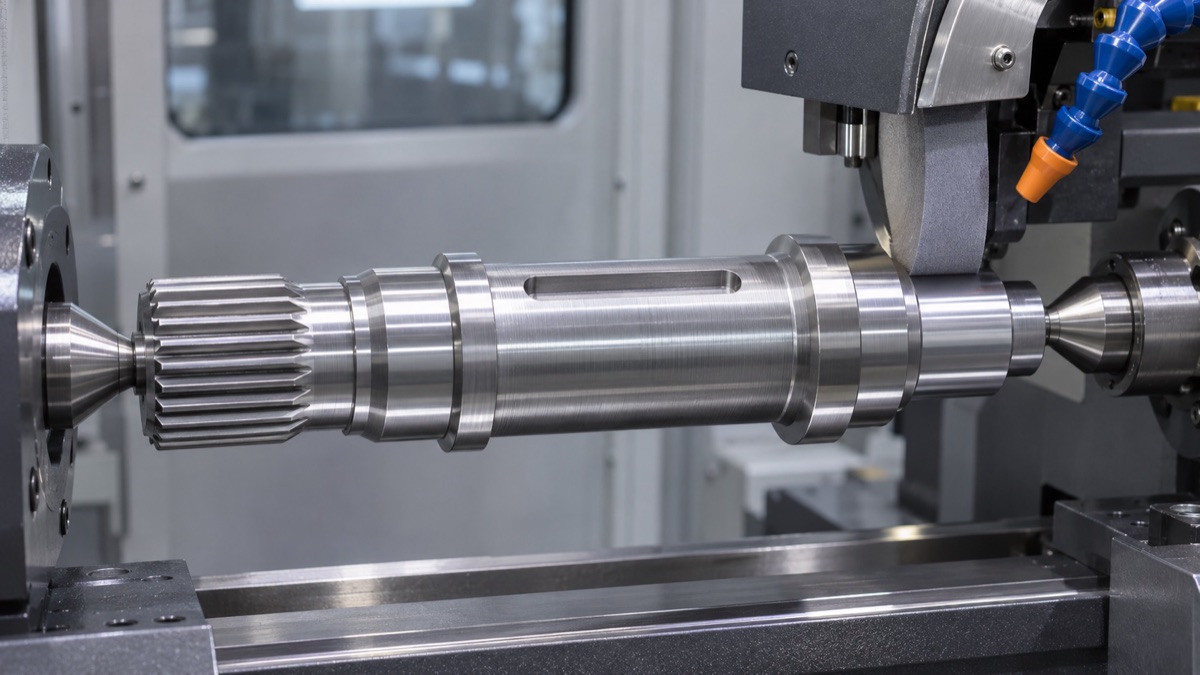
A common centerline must be protected across turning, spline cutting, heat treatment and finish grinding.
Control keyway position and balance
A keyway affects more than width and depth. Its angular position, symmetry and relationship to shoulders or timing features may control assembly and balance. Burr removal must not damage the seating edges.
Plan for heat-treatment distortion
Record straightness and center condition before and after heat treatment. Finish allowance should be feature-specific and sufficient for grinding or hard finishing without removing required case depth or leaving untreated areas.
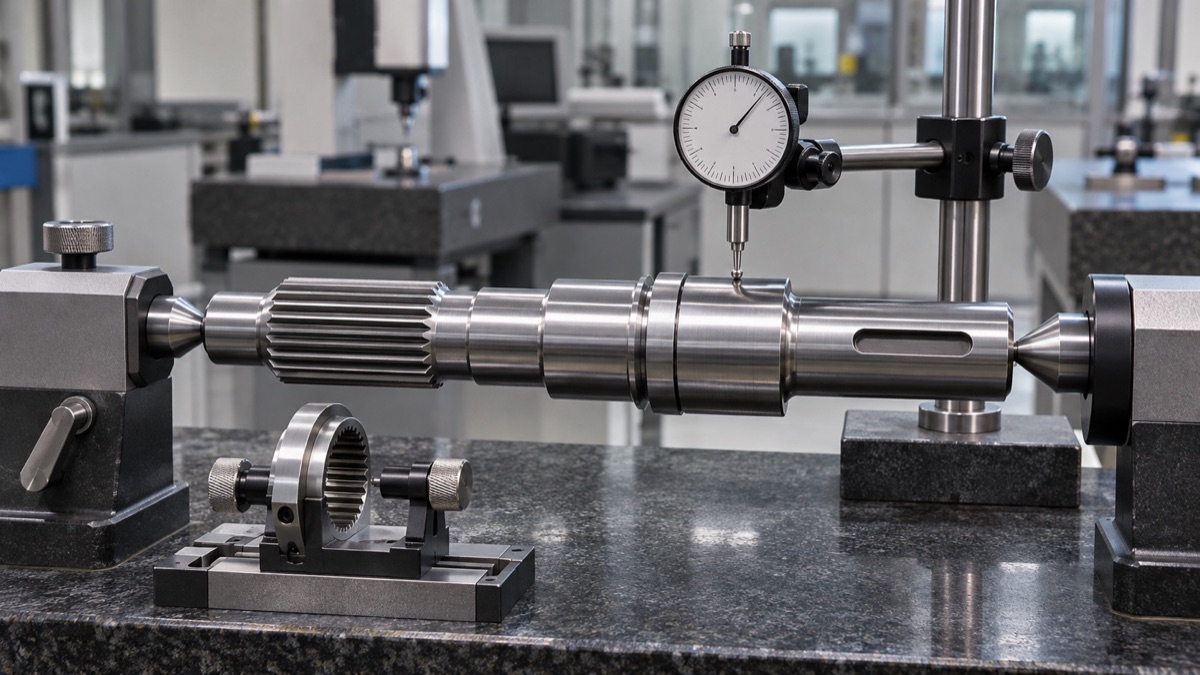
Inspection should relate journals, spline features, shoulders and keyways to the functional rotation axis.
Inspect functional relationships
Measure journal roundness and cylindricity as needed, then verify radial and face runout from the specified datum axis. Spline and keyway gauges are useful, but they cannot replace checks of axis and timing relationships.
Summary
Drive-shaft accuracy depends on one controlled rotation axis from roughing through final inspection. Spline acceptance, keyway position, heat-treatment movement and finish stock must be planned together.
FAQ
Why can a spline pass a gauge but still assemble tightly?
The gauge may not reveal burrs, lead error, misalignment to the journal axis or errors in the mating component.
Should the keyway be cut before heat treatment?
It depends on material, distortion risk and finishing route. The sequence must be validated for the specific shaft.
Can coaxiality be checked with a caliper?
No. A caliper checks size, not the relationship between axes. Use an appropriate runout setup, CMM or form measurement method.
Ready to get a quote for your CNC machined parts?
Submit your engineering drawings to qiancj@oemach.com. We support prototype sampling and small-batch production with strict tolerance control.