
A robot finger frame combines low mass with narrow ribs, deep pockets and dense micro holes. The difficult part is not making one feature in isolation, but preserving the relationship between all features after the part is unclamped.
A stable process therefore links functional datums, conformal support, staged material removal, micro-hole strategy and free-state inspection. Final parameters still depend on the alloy, stock condition and approved drawing.
Typical risks and controls
| Risk | Likely cause | Control and evidence |
|---|---|---|
| Thin-wall springback | Clamping force, unsupported areas or unbalanced stock removal | Use conformal support, limit force, release and remeasure |
| Micro-hole drift or burrs | Tool runout, unstable entry or poor chip evacuation | Use a short tool, stable entry and verified chip strategy |
| Hole shift after flipping | Inconsistent datums or setup repeatability | Keep common functional datums and verify the second setup |
Start from functional datums
Identify the mounting faces, joint axes and hole patterns that control assembly. These features should drive the setup plan. A cosmetic outside surface is rarely a reliable primary datum for a compliant frame.
Support the part without forcing its shape
Soft jaws or conformal nests should support stiff regions and leave cutting access. Apply only enough clamping force to resist cutting loads. A part that measures correctly only while clamped has not demonstrated free-state conformity.
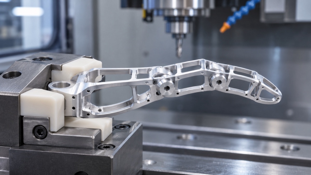
Conformal support and controlled clamping help protect the 2 mm walls during material removal.
Remove material in stages
Rough opposing regions progressively, leave balanced stock, then release and re-seat the part before semi-finishing. Finish critical walls and holes only after most internal stress and stock imbalance have been reduced.
Treat micro holes as a complete process
Control spindle and tool runout, entry stability, chip evacuation and tool wear. Hole quality also includes exit burrs and positional relationship to the frame, so visual checks alone are insufficient.
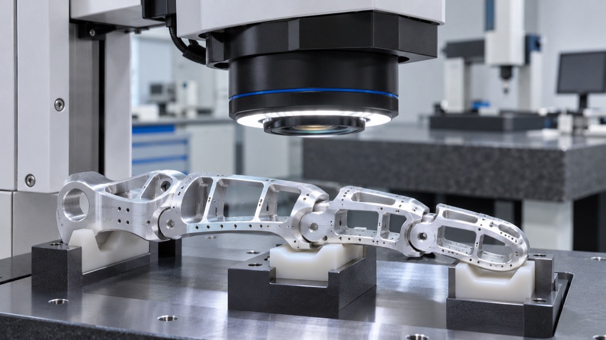
Optical and dimensional inspection should verify micro holes, wall geometry and datum relationships after release from the fixture.
Inspect after unclamping
Use optical methods where contact force could deflect the part, and report key profiles, wall thicknesses and hole locations in the free state. Record the fixture condition separately so prototype results can be transferred to production.
Summary
Reliable robot finger frames come from datum-led fixturing, low and repeatable clamping force, balanced stock removal and inspection after release. The drawing, material condition and measurement method must be reviewed together.
FAQ
Can the frame be completed in one setup?
Five-axis access may reduce flips, but a single setup does not remove the need for stress control, support and free-state verification.
Do smaller holes always require higher spindle speed?
No. Speed depends on tool diameter, material, runout, coolant or lubrication strategy and chip evacuation. Use validated tool data and trials.
Can a successful prototype process go directly into production?
Not automatically. Production requires repeatable fixtures, tool-life limits, inspection frequency and evidence from a representative pilot batch.
Ready to get a quote for your CNC machined parts?
Submit your engineering drawings to qiancj@oemach.com. We support prototype sampling and small-batch production with strict tolerance control.