
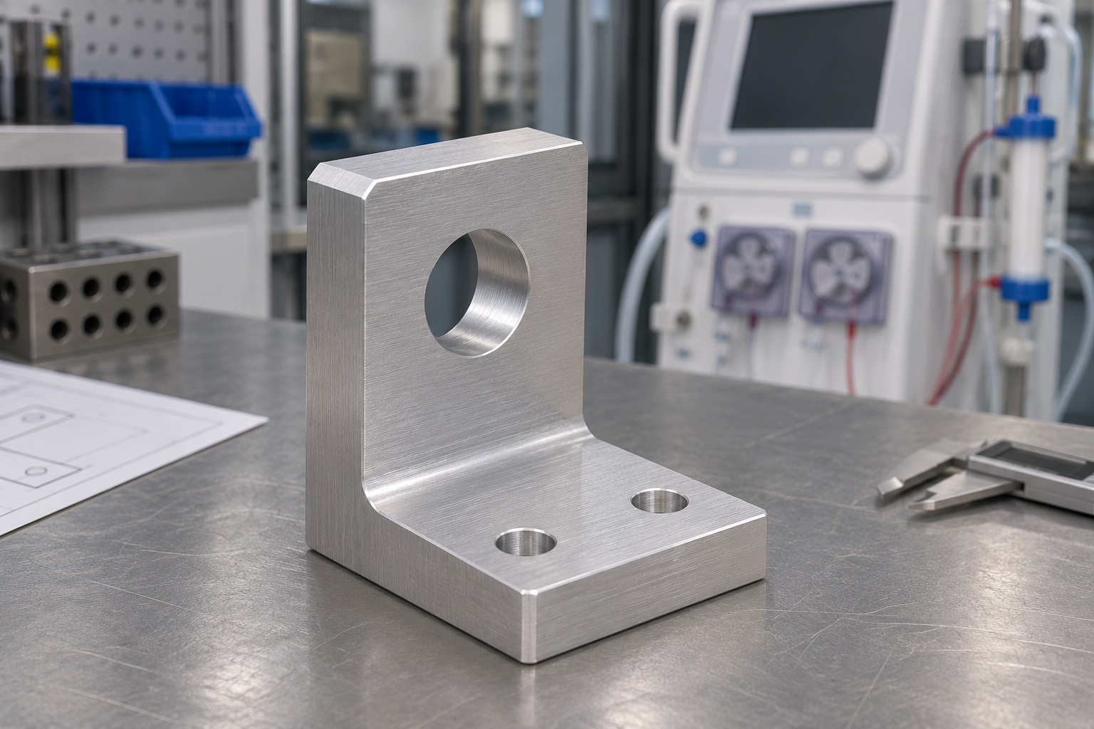
Define the scope of the dialysis console hinge bracket mockup
For CNC milling of a 6061 aluminum dialysis console hinge bracket, define the mounting plane and pin axis on the same drawing. Then review how the cross-bore position affects swing clearance on an inert bench mockup.
A dialysis console can have external covers and service panels. The bracket considered here belongs to a separate inert bench mockup and is not a spare part or a procedure for opening a clinical device. Its purpose is to study mechanical relationships such as the pin axis, mounting plane and swept clearance of a lightweight surrogate panel. Start by identifying the specific question and controlled mockup drawings. Do not infer any service requirement, interlock behavior, cabinet protection or clinical compatibility from an illustration or from the fact that a mock panel can swing.

Set the relationship between foot and axis
An L bracket can place a hinge pin above a mounting surface. The drawing should establish the foot plane and the references used to locate the bore in the upright. Bore height and angular direction are different characteristics, and either can affect a mock panel's motion. Give the inspection team a section view and explicit measuring zones. Do not treat the outside edge of an upright as the hinge axis. If a second bracket supports the same pin, the relationship between both stations should be specified relative to the same mock frame.
Separate fastening from location
The two holes in a bracket foot can retain the bracket without controlling lateral position. If the assembly must return to a precise position after removal, define a separate reference or a locating feature. Show how it interacts with the foot and frame. A pattern of holes that accepts screws does not prove bore alignment. Record whether the bracket is measured freely on a surface or fastened to the frame. A particle, raised exit edge or distorted mock frame can change the installed axis even if the individual measurements of the bracket are unchanged.
Draw the swept envelope, not just the endpoint
The hinge center and distance to a panel edge define a path during motion. A panel can clear the mock cabinet when fully open and still collide at an intermediate position. Review the known envelope with simplified section views at several positions. Identify fixed surfaces, permitted contacts and the range for the unpowered trial. Do not use the bracket as a stop unless the released mockup design specifically says so. The prototype does not establish allowable loads, required opening angle, door retention or safe access to any real dialysis equipment.
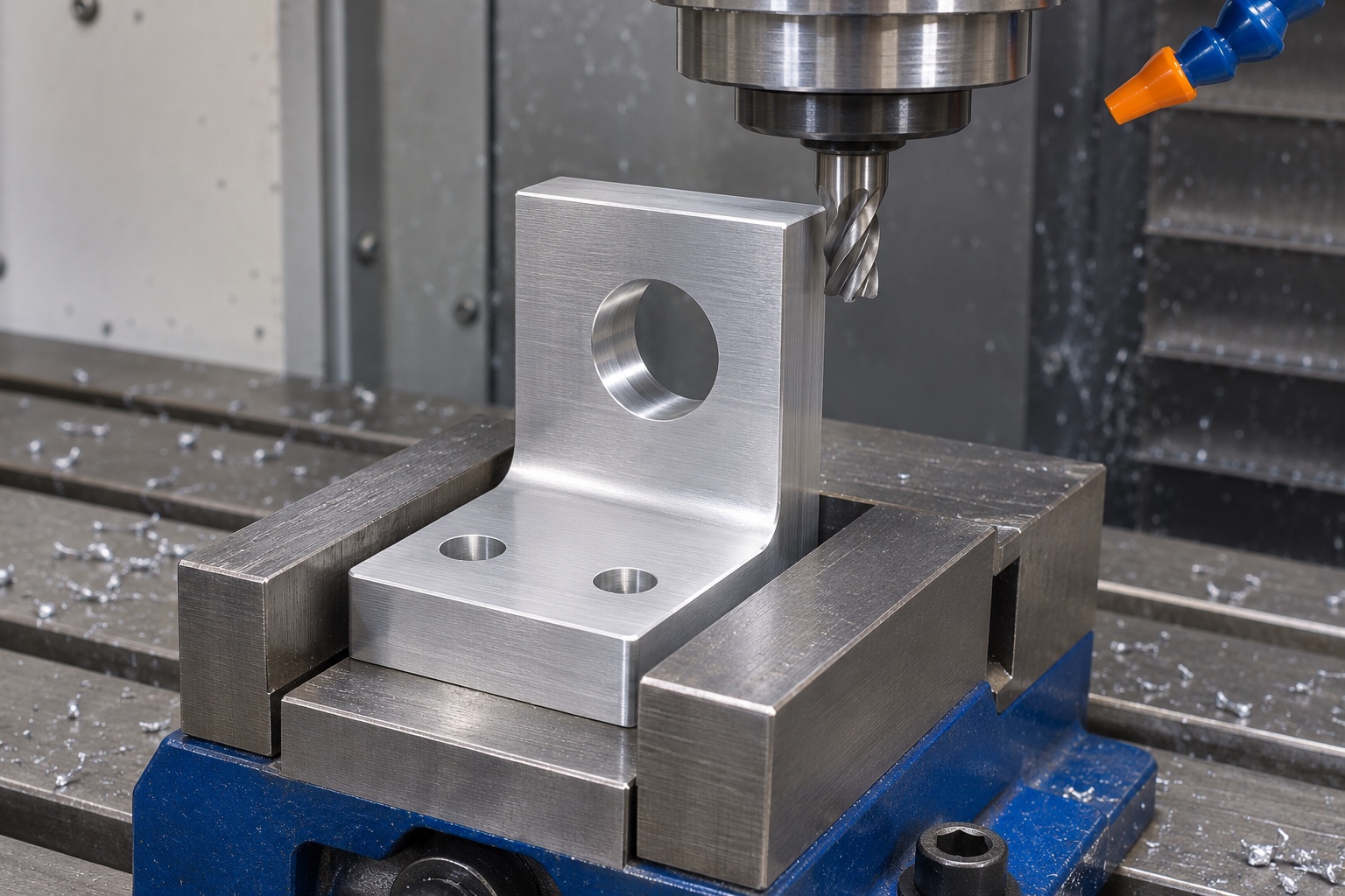
Account for the bracket's inside corner
The inner corner of an L shape may require a radius or relief for machining. Confirm the mating mock frame clears it before assigning dimensions to the upright. An apparent foot flatness problem can be caused by the upright corner touching another part. Locate the usable mounting regions away from reliefs and define access for measuring the foot. Avoid removing material from an inner corner without an approved drawing change. Any claimed structural behavior would require separate evidence; the bench fit study is limited to the specified mechanical envelope and support.
Choose grade and final finish together
An aluminum bracket can be practical for a development mockup, but the exact alloy, temper and stock form should be controlled. If a finish changes the bore, seating face or mounting pattern, specify the inspection state and any masking. A satin finish cannot establish an alloy or a coating and does not imply disinfectant compatibility, corrosion resistance, grounding or use on a medical device. Ask the design owner for any environmental or handling requirements rather than extrapolating from a generic workshop photo. Keep the identified material lot linked to the released inspection report.
Plan CNC milling and cross-bore access in a 6061 bracket
Establish the foot and stable side references before removing most of the stock around the upright. Leave finish stock where the bracket could move after release. A cross bore may require a second setup; define how the foot and side reference are transferred and how axis direction is verified. Check that cutter and probe access do not conflict with the inside corner or fixture. The machining image shows a possible access arrangement, not a cutter selection or a tolerance. Select the actual tools, supports and parameters from the released drawing and stock.
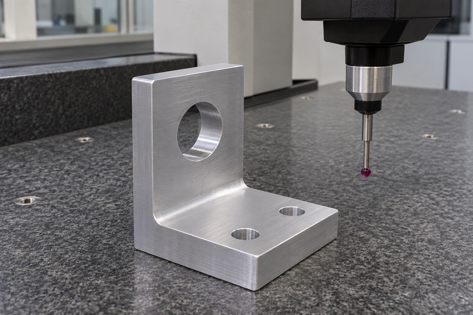
Inspect cross-bore position and panel swing clearance separately
Measure the foot condition, the hole pattern and the relationship between the cross bore and the mounting plane. Check the functional length of the bore rather than including an edge break. If the test involves a reference pin, record its identity, form and support. A pin passing through one bracket does not establish axis relationship across two mounted brackets. A controlled fit check can find interference in the assembled mockup, but it cannot replace geometric measurements. Label the inspection condition clearly so the receiving team can reproduce both records without guessing.
Use a light inert panel in a defined trial
An initial bench check can use a lightweight surrogate panel and identified pin on a separate rigid frame. Observe the specified travel and note any unwanted contact without forcing the mock assembly. Document the starting references, stop condition and any changes to the setup. If comparing two bracket samples, keep the pin and frame constant or state what changed. Do not attach the concept to a real dialysis console. A successful mechanical sweep does not demonstrate load capacity, fatigue, enclosure sealing, electrical safety or the ability to return a device to clinical service.
Find the source of an interference before rework
Check the bracket revision, pin, frame, edge condition and loose debris. A contact near the panel corner can result from axis position, panel envelope or a mismatch in the receiving frame. Measure each suspect feature before modifying the bracket. If a correction is approved, preserve the original observation and repeat the relevant checks with the same references. Widening a mounting hole can hide a position problem while reducing reproducibility. The goal is a traceable cause and a controlled comparison, not simply getting a single mock panel to move once.
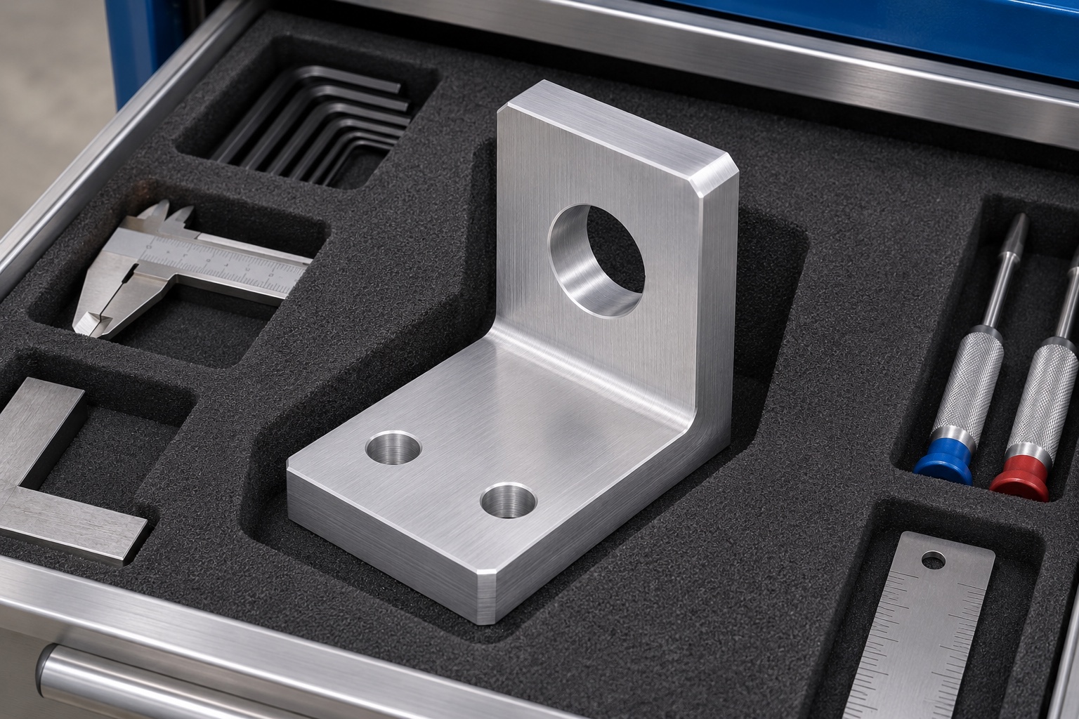
Protect seating faces in transit
Place the bracket in an insert that contacts exterior areas without levering against the upright or rubbing the mounting face. Keep pins and screws separately protected and identified. At receipt, inspect the foot, bore entry and corner for damage or debris before relying on an earlier report. Retest affected characteristics after visible impact according to the approved plan. The package provides ordinary handling protection only. It does not establish controlled cleanliness, sterility or a validated storage duration. Specify any such requirement independently and verify it with evidence appropriate to the actual use.
Request evidence the CNC supplier can provide
Send the controlled bracket, frame and surrogate panel drawings, material and finish, references, measuring zones and permitted trial conditions. Request measured geometry and separate sweep observations if needed. A supplier should list any unresolved interfaces or support conditions rather than assume compatibility with a real product. Service instructions and equipment safety remain with the responsible equipment owner. The value of the mockup is that another team can repeat the same mechanical comparison and see which conclusions it does and does not support.
FAQ
Is this a spare bracket for a dialysis console?
No. It is an offline CNC mockup concept and does not authorize installation or service on a real device.
How does cross-bore position affect panel swing clearance?
The cross-bore location and direction establish the mock pin axis. The panel envelope then defines the swept clearance.
Does a pin fit prove the installed hinge is aligned?
No. It is a local observation unless the full mounted reference and both support stations are checked as required.
Why check motion between the endpoints?
An edge can collide during travel even when it clears at both endpoints. Record the location and setup of any contact.
Does the trial establish load capacity?
No. It uses a lightweight inert panel to check geometry only. Structural and device safety evidence is outside its scope.
Is the protective insert a sterile packaging system?
No. It is ordinary mechanical protection for shipping and does not establish a cleanroom class or sterile condition.

tanghangyun@oemach.com