
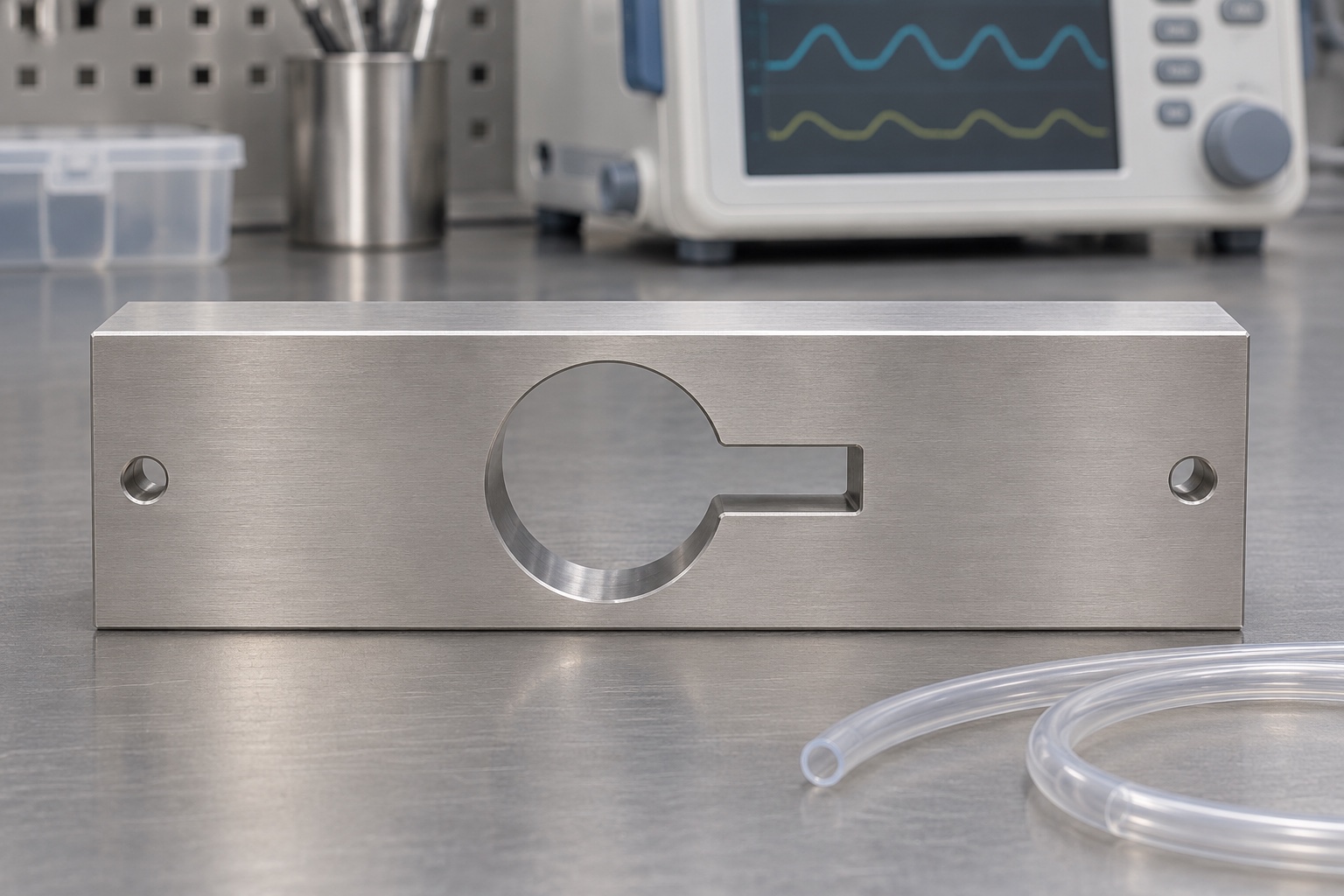
Define the scope of the capnography connector gauge
For 316L CNC machining of a capnography connector gauge, start with the drawing datums and distinguish the dimensions of the round opening from those of the key before choosing tools or inspection methods.
Capnography systems can use dedicated sampling lines and connectors. An offline envelope gauge can answer whether a rigid surrogate enters a specified outline in a documented orientation. It cannot establish that a sample line fits a named monitor, seals, or measures carbon dioxide correctly. Define which feature is compared: the outside envelope, the angular key, the depth of insertion or the clearance around a collar. Each has its own measurement reference. The generic gauge here does not connect to tubing, respiratory gas, a patient or an operating device.

Identify the key's purpose
A key can restrict orientation without carrying the load or setting depth. A drawing should distinguish a key flank that intentionally guides the surrogate from a relief that must not touch it. A keyhole-like silhouette can combine a round opening and a narrower side relief, but the two cannot be treated as one nominal diameter. Show the section and approach direction. Confirm what part of the surrogate is allowed to reach the rear of the gauge and what must remain clear at intermediate positions, not only when fully inserted.
Establish position from functional datums
Relate the aperture and key to a base plane, side and end reference that an inspector can reconstruct. If two mounting holes are only for retention, they need not be precise location features unless the design says otherwise. If the gauge must return to a position after removal, specify a distinct locating feature or an approved inspection setup. Record whether the gauge is free on a plate or bolted down. A tilt from mounting or debris can change an apparent clearance without any change in the opening itself.
Separate clearance from acceptance by force
Specify the shape of the inert reference and the limits it represents. A single reference that passes may not exercise the limiting key width, body diameter or collar length. A soft part pushed through a tight opening can deform, so the same motion need not represent the same geometry. Use the agreed handling condition and record any unintended contact instead of forcing insertion. If a screening gauge is intended to give only a go or no-go result, do not present that observation as measured size or true position.
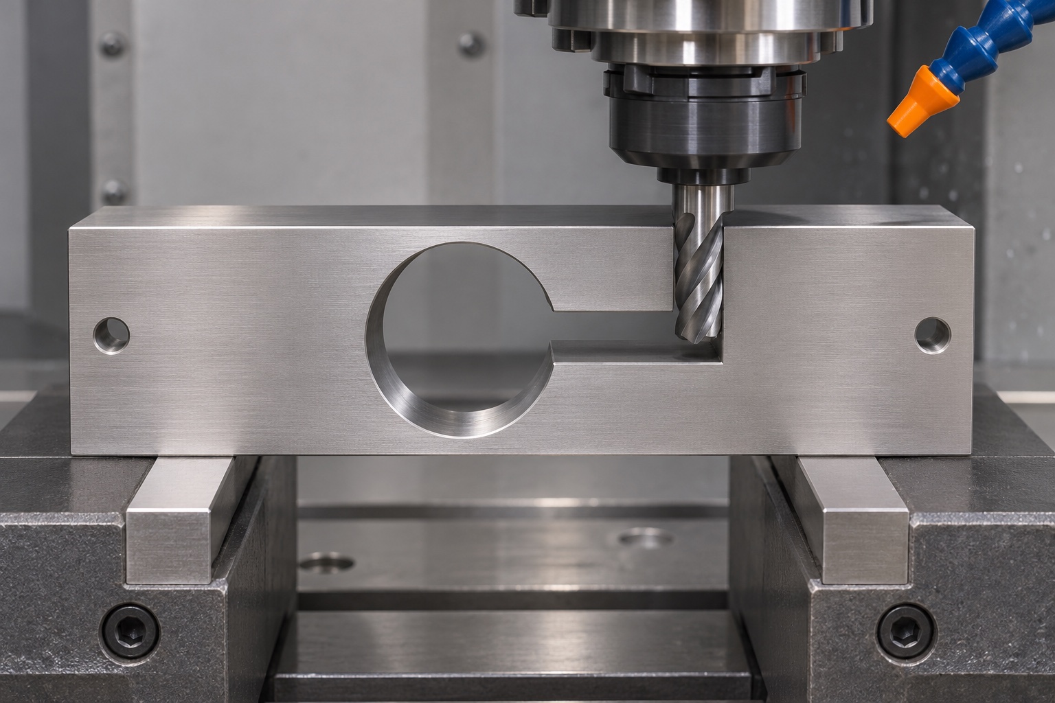
Provide usable relief at internal corners
A cutter leaves a radius where an ideal drawing may show an intersection. Model the radius with the key and the opening at their allowed limits. A relief outside the functional flank can give the key clearance while preserving a defined guiding surface. Make any relief visible on the drawing and show what may not be touched during measurement. Avoid increasing the whole opening to fix one corner unless the design owner reviews the result. Too much clearance can make the gauge unable to detect the geometry it was designed to screen.
Select the grade and finish for bench handling
Stainless steel can provide durable surfaces for repeated contact with a rigid surrogate. The actual grade, stock condition, finish and inspection state still need to be stated. A machined face does not prove resistance to a particular cleaning agent or compatibility with a clinical environment. If the gauge is intended for defined cleanliness at receipt, specify the condition separately from the material. The device owner must evaluate any patient-contact or gas-path materials; those questions are not answered by this gauge and are not part of the illustrated bench setup.
Plan CNC machining for the round and keyed openings
A round section and key relief can be produced from a common origin where practical. Establish the base and sides, rough the opening with enough stock for finishing, then check the blank after release if clamping could distort it. Finish the critical flanks and opening while preserving their relationship. If turning, drilling, milling or another operation transfers the part to a second setup, define how the origin is reestablished. The shown machining scene illustrates access, not a recommended cutter, feed or finished tolerance. Choose the process from the released geometry and material.
Dimensional inspection of keyed openings in 316L gauges
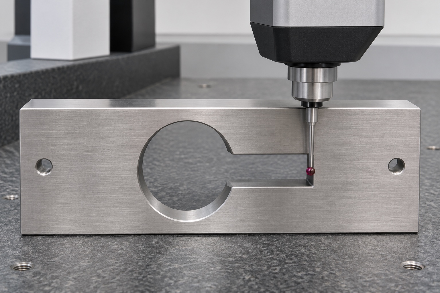
Measure the round region in the usable length, not on an entry chamfer. Check key width, location and any specified angle separately. Review access for a probe to the flank and the junction radius. A single plug that enters the opening cannot confirm all of these relationships. Check the entry and exit for raised material after any approved edge break. The report should say which measurements were taken in the free state and which in the installed bench arrangement, with identified stations or sections for repeat inspection.
Perform a dry trial with identified surrogates
Use a labeled inert reference and orient it using the drawing. Observe insertion, intended contact and removal without a line, gas supply or powered monitor. Try only the orientations specified in the inspection plan. Note whether an interference follows the surrogate or appears at the same point in the gauge. If the purpose is to investigate angular keying, document the limiting contact and preserve the reference pieces. A successful dry trial does not establish leakage, flow response, instrument compatibility, alarm behavior or suitability for patient use.
Diagnose an obstruction before altering the profile
If the reference stops early, inspect for debris, a raised edge, a mismatched revision or a local radius conflict. Compare the relevant measured geometry with the drawing. Do not file the key or widen the opening simply to make a single reference pass. An authorized correction should preserve a record of the original condition and trigger remeasurement of any affected characteristic. A repeat trial is useful only when the support and reference are identified. A change in handling force or orientation can otherwise obscure the cause of an apparent improvement.
Protect the reference surfaces during storage
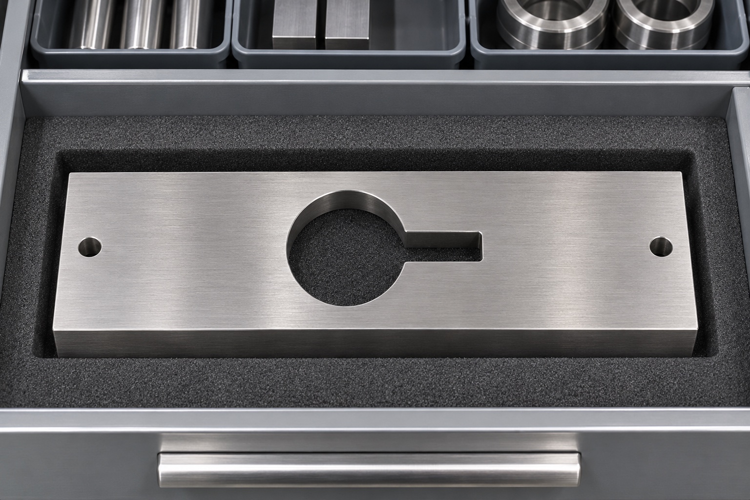
Support the block at suitable exterior areas and keep hardware out of the aperture. A fitted insert can reduce impact and abrasion without contacting the key flank. Keep the gauge and surrogate identifiers separate and link both to the inspection record. At receipt, inspect for a shifted insert, loose material or damage and repeat affected checks. This is ordinary shop protection, not a sterile barrier or a storage-life validation. Any defined cleanliness requirements need their own controls and acceptance evidence, independent of the packaging illustration.
Make a useful handover for the next inspector
Send the controlled gauge and surrogate drawings, material and finish, mounting references, measurement stations and dry-trial conditions. Ask for separate records of geometry and mechanical fit. Identify which expected conditions have not been tested. A bench gauge is useful when another person can reconstruct the exact check, not when the record extends the result to device performance. The responsible equipment owner must determine whether a real sampling line is suitable and follow its approved methods. No customer, certification or measured instrument result is implied by the example.
FAQ
Is the gauge a capnography adapter?
No. It is an offline mechanical envelope gauge. It does not connect to a monitor or carry a gas sample.
Does the round opening set the key angle?
Not by itself. The angular reference and key flank must be defined and inspected relative to the drawing's datums.
Can an inert surrogate establish a leak rate?
No. It can show selected mechanical contacts in the bench setup, not sealing, flow or instrument accuracy.
Why inspect the keyed opening and bore diameter separately?
A reference can clear one feature while binding on the other. Separate measurements identify where any mismatch occurs.
Can a burr be removed after the fit trial?
Only under an approved correction. Remeasure affected features and repeat the trial with the same documented references.
Does a protective insert imply sterile delivery?
No. It protects the geometry from ordinary handling damage; cleanliness classification and sterility require separate evidence.

tanghangyun@oemach.com