
Two bearing bores can each pass their diameter tolerance and still fail in assembly because their axes do not share the required relationship. The result may be preload, heat, noise, shortened bearing life or unstable joint motion.
A 0.01 mm coaxiality requirement is not a general shop claim. It is a project-specific geometric requirement whose meaning depends on the drawing standard, datum system, controlled length and inspection method.
The most reliable process connects design intent, fixture strategy, material stability, final bore finishing and CMM evaluation in one traceable datum chain.
Main risks when controlling bearing-bore coaxiality
| Control area | Typical failure | Practical response |
|---|---|---|
| Drawing and datums | Ambiguous axis control or inspection by best fit | Define the assembly datum, controlled bore length and applicable GPS or GD&T requirement |
| Setup strategy | Axis shift after refixturing | Finish related bores in one setup where practical or qualify the transferred datum |
| Material removal | Stress release moves a finished bore | Use balanced roughing, stock allowance, stabilization and delayed finishing |
| Clamping and heat | Thin walls distort during cutting or measurement | Support near load paths, limit clamp force and control part temperature |
| Inspection | Size passes while axis relation fails | Measure size, form, position and orientation with the same functional alignment |
Define What 0.01 mm Means On The Drawing
Start with the assembly function. Identify the primary mounting face or pilot that establishes the joint, then define how both bearing axes relate to that datum and to each other.
The term coaxiality may be interpreted differently under ASME Y14.5 and ISO GPS practices. Position, runout or a coaxial axis requirement can lead to different evaluation methods. The released drawing should state the datum reference frame, tolerance zone, controlled feature length and measurement condition.
A supplier should not convert 0.01 mm into a blanket machine capability statement. Bore diameter, length, spacing, wall thickness, material, access and temperature all affect feasibility.
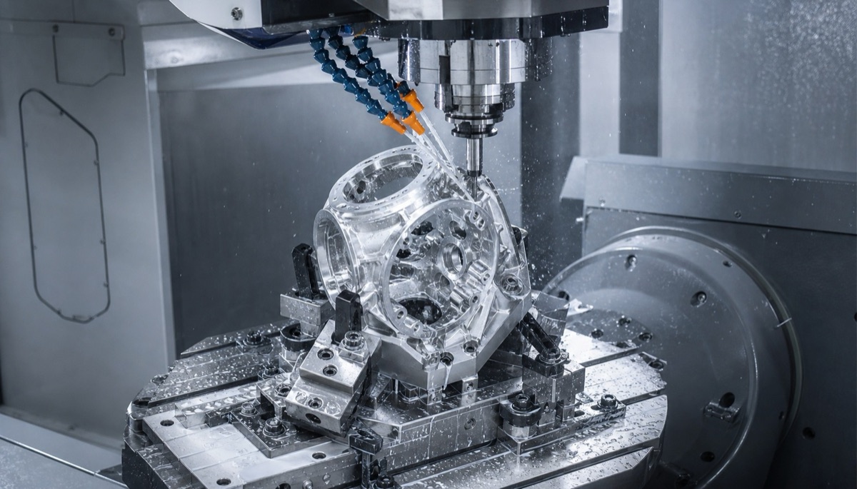
Related bearing bores should be finished from a common datum system or through a verified datum-transfer process.
Use One Setup Or A Verified Datum Transfer
When tool access permits, finishing both bearing bores in one setup gives the shortest datum chain. Line boring, fine boring from opposite directions with a controlled centerline, or a dedicated boring arrangement can keep the axes related to the same work offset.
If the component must be turned over, the second setup should locate on functional, repeatable surfaces rather than rough stock. Qualified pilots, precision fixture references, probing and an intermediate verification step reduce transfer error. The process plan should include the expected fixture repeatability in the tolerance budget.
Separate Roughing, Stabilization And Bore Finishing
Robot bearing housings often contain pockets, ribs and unequal wall sections. Heavy stock removal can release residual stress and change the relationship between bores after they appear complete.
A robust route roughs the housing symmetrically, leaves controlled stock on critical bores and faces, allows the part to stabilize where needed, and then establishes the functional datums before final finishing. Fine boring offers adjustable size and axis control; reaming can improve size in a well-prepared straight hole; grinding or honing may be selected when form, finish or hardened material requires it.
The finishing method should be chosen from the complete requirement, not the nominal bore tolerance alone.
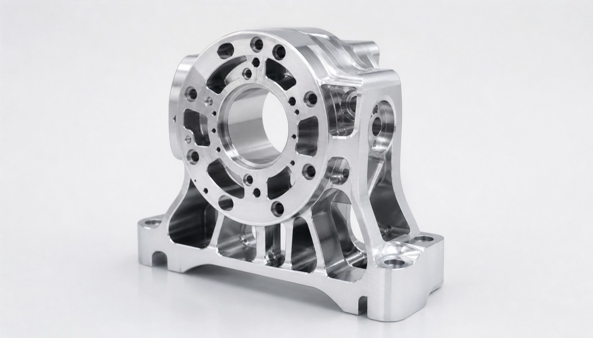
Stable coaxiality depends on the complete route: material condition, support, roughing, stabilization, finishing and temperature-controlled inspection.
Control Clamp Distortion And Thermal State
A thin bearing wall can become round under the cutter but relax out of round after unclamping. Fixture supports should follow the structural load path, and clamp force should be repeatable and no higher than necessary. Soft jaws or distributed supports may be useful when their contact is verified.
Cutting heat, wash temperature and inspection-room temperature can also consume a significant part of a 0.01 mm budget. Final cuts should use stable tool condition and coolant control. The part should reach the specified measurement temperature before acceptance, especially when aluminum housings and steel masters are compared.
Inspect Size, Form And Axis Relationship Separately
A bore gauge confirms diameter at selected sections but does not prove the relationship between two axes. Roundness or cylindricity data may be needed to understand local form, while a CMM evaluates axis position and orientation in the assembly coordinate system.
The CMM program should align to the released datum reference frame rather than independently best-fit each bore. Measurement point distribution, usable bore length, filtering, probe qualification and temperature compensation should be agreed for critical work. A functional master or trial assembly can supplement dimensional data, but it should not replace the drawing requirement.
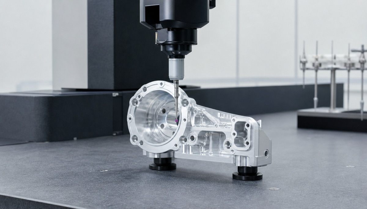
Inspection must reproduce the assembly datum and evaluate bore size, axis position and axis orientation separately.
Information To Include With The RFQ
The feasibility review becomes faster and more accurate when the supplier receives the functional context with the model.
- 2D drawing and 3D model with matching revision
- Applicable GD&T or ISO GPS standard and exact datum reference frame
- Bearing type, fit, preload concept and mating shaft or cartridge
- Bore diameter, controlled length, spacing and access direction
- Material, heat treatment, casting or extrusion condition and surface treatment
- Required CMM report, sampling plan, measurement temperature and trial-assembly needs
Summary
Stable 0.01 mm coaxiality is achieved by defining the functional datum, minimizing or qualifying setup transfers, allowing the housing to stabilize before final bore finishing, controlling clamp and temperature effects, and inspecting all related axes in one assembly-based coordinate system.
FAQ
Can two bearing bores pass size but fail coaxiality?
Yes. Diameter is a local size requirement; coaxiality or position controls the relationship between the two bore axes.
Must both bores be machined in one setup?
One setup is preferred when geometry and access allow it, but a qualified fixture and verified datum transfer can also work when a second setup is unavoidable.
Is reaming enough for 0.01 mm coaxiality?
Reaming follows the prepared hole and is mainly a size and finish process. It cannot reliably correct a significant axis error, so upstream boring and datum control remain essential.
Why should inspection use the assembly datum?
The bearing system functions relative to mounting faces and pilots. A best-fit alignment can hide the same axis error that causes preload or misalignment in assembly.
Ready to get a quote for your CNC machined parts?
Submit your engineering drawings to qiancj@oemach.com. We support prototype sampling and small-batch production with strict tolerance control.