
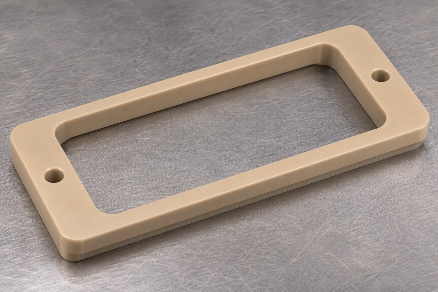
Start with the dry-side interface
A perimeter keeper can retain the external flange of a replaceable microfluidic cartridge without becoming part of its internal fluid circuit. The distinction matters on the drawing: show which faces may touch the cartridge and which must remain clear of its membrane, ports and optical windows. An open center does not guarantee that those zones remain clear after installation. A corner radius, screw head or underside step can intrude once the mating flange shifts to the extreme of its tolerance. Use the cartridge and equipment drawings together to establish the allowable envelope.

Decide what locates and what retains
A retaining frame should not be made responsible for every direction of location by default. Define the primary seating plane in the equipment, the surfaces that set lateral position and the feature that controls insertion direction. The keeper may then supply an axial stop without squeezing the cartridge between opposing walls. If a screw hole is intended only for clearance, do not use its axis as a locating datum. Unintentional constraints make an assembly appear tight at one tolerance combination while letting it rock or bind at another.
Allocate the clearance deliberately
Build the clearance analysis around functional sections rather than around one nominal opening dimension. A top view can miss an interference below the cartridge flange. Compare the narrowest useful opening, inner corner radii and underside ledge with the largest mating envelope in the relevant assembly condition. Include permitted lateral offset and approach angle. Where the cartridge is installed by hand, account for how the operator grips it and how the frame is removed for service. The design team, not the machining supplier alone, must decide the acceptable balance between movement and insertion margin.
Separate retention from sealing
A dry-side keeper does not validate a cartridge seal. If the instrument uses a separate gasket, spring, latch or compression actuator, define that mechanism independently and avoid loading it inadvertently through the keeper. A photograph of a closed assembly cannot demonstrate seal compression or leakage resistance. On the keeper drawing, describe the approved flange contact band, the no-contact zones and any limits on transferred load. Treat unexpected marks on a dummy cartridge as a design-review finding rather than an invitation to increase fastener torque or remove material locally.
Specify the polymer stock and conditioning
Specify the PEEK grade, stock form and relevant lot documentation rather than relying on appearance. Natural color is not a material identification method. The supplier's machining guidance can inform discussion of stress relaxation, temperature and stock orientation, but it does not approve the finished application. Check whether the engineering drawing requires a particular heat history or conditioning state before measurement. Confirm all proposed cleaning agents and exposure conditions with the equipment owner. A stock certificate cannot establish patient contact suitability, assay compatibility or finished-system approval.
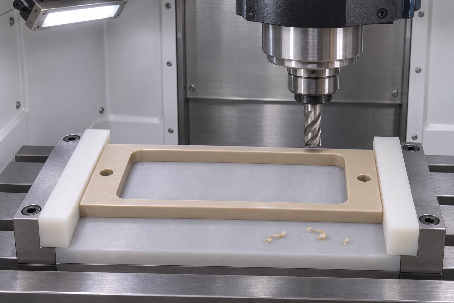
Support thin webs during milling
When most of the center is removed, the remaining long sides can move under fixture pressure. Plan the cut sequence so that a stable outer support remains during roughing and the part can be released before final inspection. Broad contact areas on the fixture are generally easier to manage than a hard point load at a narrow corner. Select a cutter that clears the inner corners and carries chips away without rubbing. Evaluate stock removal and clamping on a trial piece instead of assuming a flat, unclamped frame from a reading taken in the vise.
Keep the underside step measurable
The retaining step should have a defined depth from a named reference face and a defined useful contact width. Distinguish its flat contact band from the blend at the inner wall. A probe or depth gage that sits on that blend can create a plausible but incorrect result. Include tool clearance where the step approaches an internal corner and decide whether an interrupted contact band is permitted. If a drawing calls for an unspecified sharp corner, clarify the actual functional requirement before selecting a machining method or quoting a tolerance.
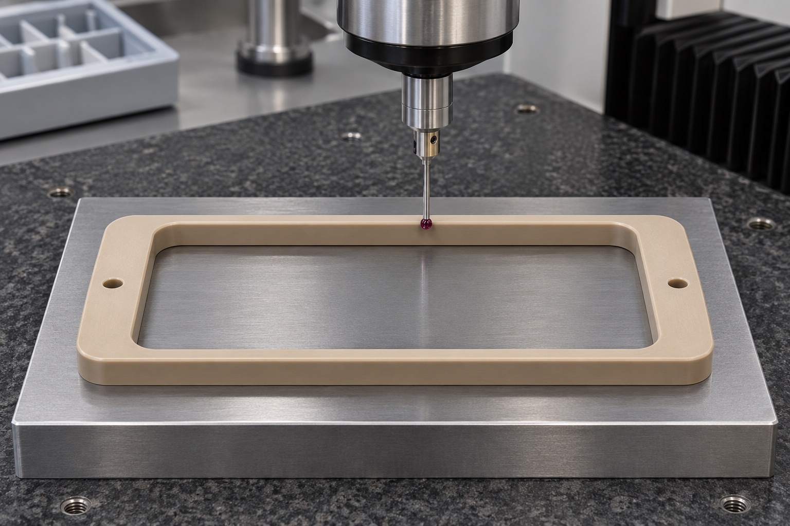
Measure the released geometry
Inspect the keeper after it has been removed from the fixture and reached the agreed measurement condition. Support it at the points defined in the inspection plan, without forcing all corners down. The drawing may distinguish local ledge height from global free-state form; report the results separately. A height map shows where the frame rises or twists, while an opening profile checks clearance relative to the installation datum. A low-force probe or suitable optical method helps avoid a contact reading that changes the shape it is intended to measure.
Verify seating with a defined surrogate
Use a clean, dimensioned surrogate to examine whether the planned contact band seats and whether removal remains practical. Record the surrogate revision, mounting condition and the observed contact locations. A surrogate is a check of the mechanical interface, not a substitute for dimensional inspection. Do not put a working cartridge or reagent sample into a machining area to perform this check. Where the application needs force, leakage or cycle testing, the design team should define those tests using the complete, intended instrument assembly.
Define edge treatment by zone
An edge that an operator touches, an edge facing a cartridge flange and a nonfunctional outer corner need not receive the same treatment. Uncontrolled scraping can shift the useful opening or widen a shallow contact band. Mark the edges that must be broken and any surfaces on which marks are unacceptable. Inspect the window corners, mounting holes and underside step after deburring. Loose chips can be trapped at the recess transition even when the broad faces look clean, so the cleaning and inspection plan should name the areas to examine.
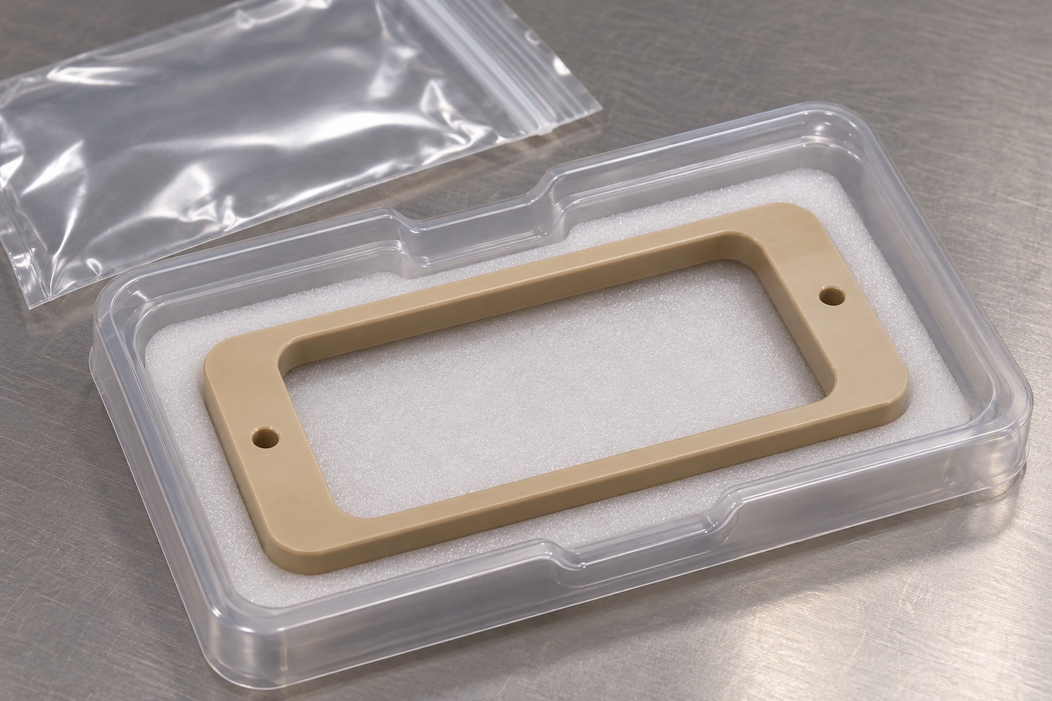
Protect the frame without loading it
Support the perimeter in transit without wedging the keeper into a tight pocket. Individual separation protects the step and inner edge from impact by adjacent parts. Agree on the cleanliness level, bag material and labeling before production; packaging chosen to control ordinary handling contamination is not a sterile barrier. Keep labels and adhesive away from contact faces. If a frame arrives bent or with damaged edges, quarantine it for inspection instead of pressing it flat, since the released geometry is part of the functional acceptance decision.
Make the RFQ measurable
Provide the cartridge drawing, equipment seat model, keeper revision, material specification, approved contact map and required inspection state. Include the intended assembly and cleaning conditions, and ask the supplier to identify what will be measured in the fixture and what must be measured after release. Request a first-article report with coordinates or feature identifiers that match the drawing. When the opening, ledge and hole pattern each have a clear function, engineering can resolve an interference by addressing its source instead of tightening every tolerance on the frame.
Manufacturer background reference: www.ensingerplastics.com.
FAQ
Does the keeper touch the sample?
The concept is confined to the dry external flange of a cartridge. If a different assembly creates contact with fluid, reagents or a patient, that change requires separate material, cleaning and application assessment by the equipment owner.
Why measure the frame outside the vise?
Fixture pressure can flatten or bend thin webs. A released measurement on defined supports represents the free-state form; an in-fixture measurement answers a different process-control question. State both conditions explicitly when the project uses both readings.
Can the two screw holes locate the opening?
Only if the assembly and drawing actually use them for location. Plain clearance holes generally permit movement. If a seat edge or dedicated locator defines installation, reference opening profile and position to that functional datum instead.
How should the underside ledge be checked?
Measure depth from the specified reference and take readings on the usable band, away from the blend. A calibrated depth or coordinate method should be able to access that region without deflecting the frame or riding on the corner radius.
Does a fit check demonstrate seal performance?
No. A surrogate fit check can identify interference or unexpected contact on the dry side. Seal compression, leakage and cartridge function are separate verification activities on a defined assembly and must have their own requirements and evidence.
What should the protective package accomplish?
Keep the edges and contact band from striking other parts, avoid bending the thin webs, and limit handling contamination according to the agreed specification. Nonsterile protective packaging does not establish sterility, cleanroom processing or validated shelf life.

tanghangyun@oemach.com