
A robot wrist packs several rotational interfaces, bearings, reducers, fasteners, sensors and cable paths into limited space. A local dimension can pass inspection while the assembled axes still accumulate alignment error.
The machining plan must therefore control relationships between bearing bores, mounting faces, angled hole patterns and locating features from a common assembly datum system.
Five-axis machining can reduce datum transfers, but stiffness, process sequence, edge condition and a functional inspection plan remain just as important.
Critical controls for compact robot wrist parts
| Design area | Primary risk | Machining and inspection response |
|---|---|---|
| Bearing and pivot bores | Axis offset, angular error and fit variation | Finish from related datums and inspect axis position, orientation and size |
| Multi-side interfaces | Accumulated error across repeated setups | Use five-axis or controlled 3+2 indexing with verified datum transfer |
| Cable and sensor routes | Sharp edges, blocked clearance and connector interference | Control slot position, edge breaks, burrs and assembly envelope |
| Thin housing walls | Clamp distortion, chatter and stress release | Balanced roughing, distributed support, rest or stabilization and light finishing |
| Tool and reducer flanges | Runout, face error and clocking mismatch | Common-axis finishing and CMM or functional assembly verification |
Control The Wrist As An Axis Stack
A wrist housing and adapter flange connect multiple joints in a short distance. Bearing centers, reducer pilots, motor seats and output flanges form an axis stack that defines motion and load transfer.
The drawing should establish a primary mounting face and axis, then locate secondary axes and clocking features from that system. Independent best-fit inspection of each face can hide accumulated assembly error.
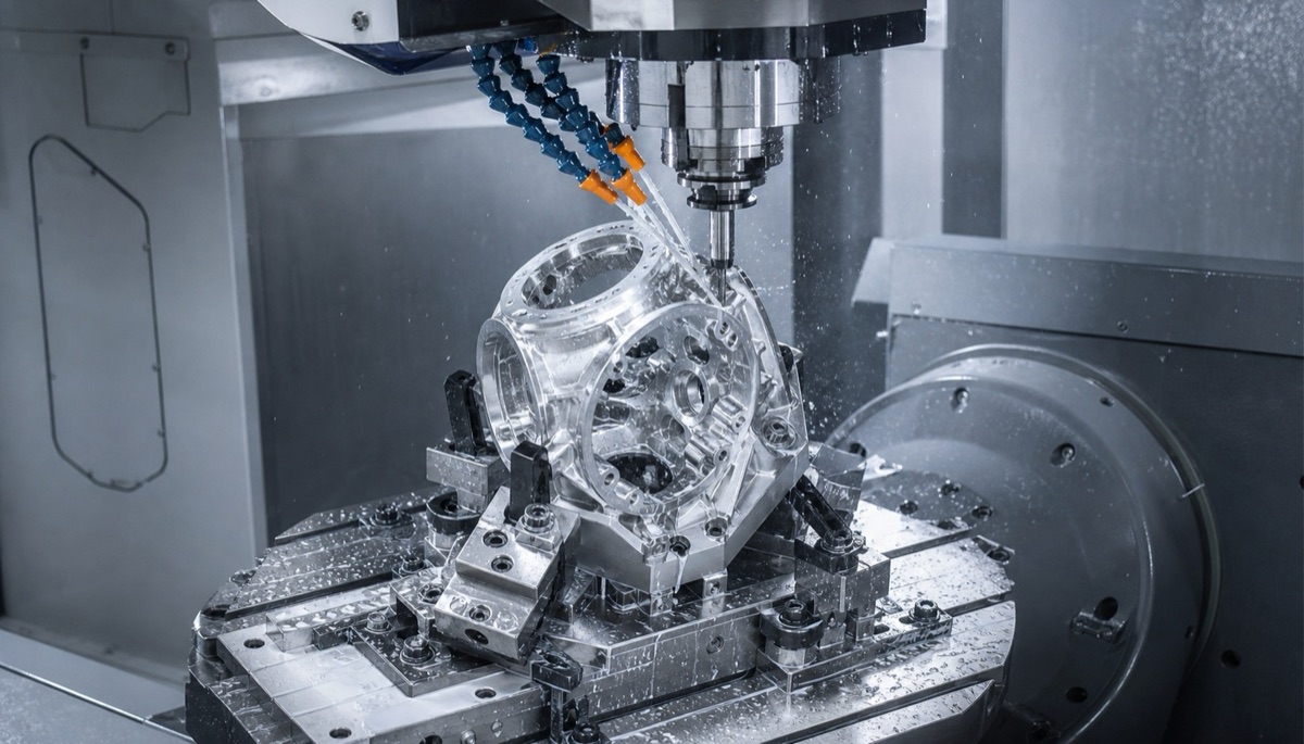
Five-axis or 3+2 positioning can keep bearing bores, angled interfaces and side-hole patterns in a controlled datum chain with fewer setups.
Five-Axis Machining Reduces Datum Transfers
True five-axis cutting or 3+2 positioning can reach angled bores, side faces and hole patterns without repeatedly removing the part. Fewer setups reduce fixture accumulation and keep features related to one measured work offset.
Five-axis equipment does not guarantee accuracy by itself. Rotary-axis calibration, tool-center control, fixture stiffness, probing strategy and thermal condition determine whether the geometric advantage reaches the part.
Thin Walls And Deep Pockets Need A Staged Route
Compact wrist parts often remove large volumes of aluminum to reduce inertia, leaving ribs, bosses and suspended walls. Heavy one-sided cutting can release stress and move bearing or flange features.
Balanced roughing leaves material around functional interfaces, followed by a rest or stabilization step where needed. Semi-finishing establishes the structure; bearing bores, faces and locating holes are finished only after the housing becomes stable.
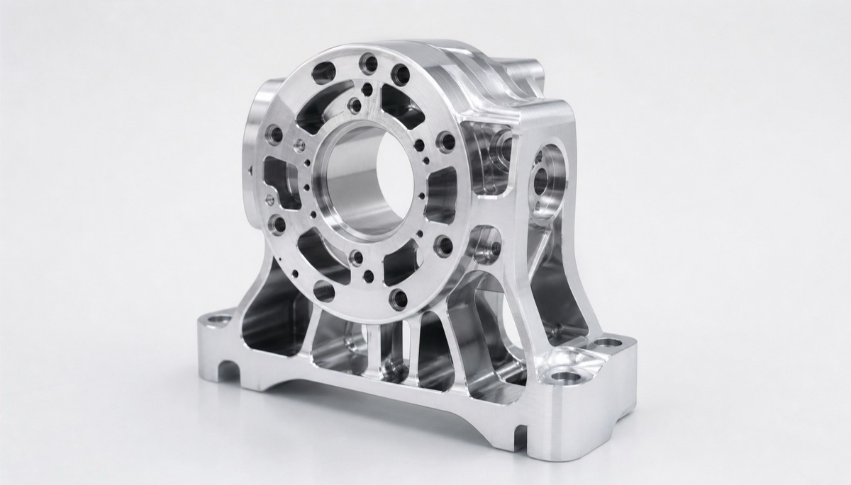
Compact pockets, ribs, cable clearances and bearing interfaces require a balance between low mass, stiffness, edge safety and inspectability.
Cable Routing Is A Precision And Reliability Feature
Cable slots, sensor passages and connector pockets must maintain clearance through the wrist motion envelope. A slot that is dimensionally acceptable can still abrade a cable if its edge break, burr direction or local alignment is wrong.
The process specifies edge condition, deburring access and protected routing surfaces. The assembly review should include the actual cable diameter, bend radius, connector size and any moving cover or strain-relief feature.
Inspect Relationships, Not Only Individual Sizes
CMM inspection should align to the functional datum system and report bearing-axis position, angular relationship, reducer-seat and flange runout, mounting-face orientation and critical hole patterns. Bore gauges and thread gauges provide direct functional size checks.
A first-article build with mating bearings, reducers, dowels or a master fixture can reveal cable and assembly conditions that coordinate data alone cannot describe. Results should remain traceable to the released drawing revision.
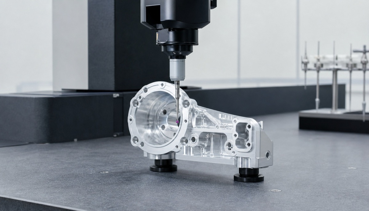
The measurement alignment should evaluate bearing axes, reducer seats, mounting faces and multi-side holes in the same assembly coordinate system.
Information To Confirm Before Quotation
A complete RFQ lets the supplier plan datum access, fixtures, tools and inspection before assigning cycle time.
- Released 2D drawing and 3D model with the same revision
- Primary joint axis, mounting datum and secondary-axis relationships
- Bearing, reducer, motor, sensor and output-flange mating conditions
- Material, temper, heat treatment, thin-wall zones and finish
- Cable diameter, routing envelope, connector clearance and required edge breaks
- First-article scope, CMM report, functional gauges and repeat-batch sampling
Summary
Robot wrist precision depends on the relationship between several axes and interfaces inside a compact, lightweight housing. A shared datum system, fewer controlled setups, staged material removal, safe cable features and relationship-based inspection are more important than simply tightening every local dimension.
FAQ
Why are robot wrist parts often made on five-axis machines?
Multi-side bores and angled interfaces can be reached with fewer setups, reducing datum-transfer error and keeping related features in one coordinate system.
Does five-axis machining automatically guarantee wrist accuracy?
No. Rotary calibration, fixture stiffness, probing, tool control, temperature and the process sequence still determine the final result.
How is accumulated axis error controlled?
Define a primary assembly datum, locate secondary axes from it, machine critical interfaces through a controlled datum chain and inspect all axes in the same coordinate system.
Why are cable slots included in precision planning?
Position, clearance, edge condition and bend space affect cable life and full-range wrist motion, even when they are not the tightest dimensions on the drawing.
Ready to get a quote for your CNC machined parts?
Submit your engineering drawings to qiancj@oemach.com. We support prototype sampling and small-batch production with strict tolerance control.