
Separate the housing body from the spring-loaded assembly
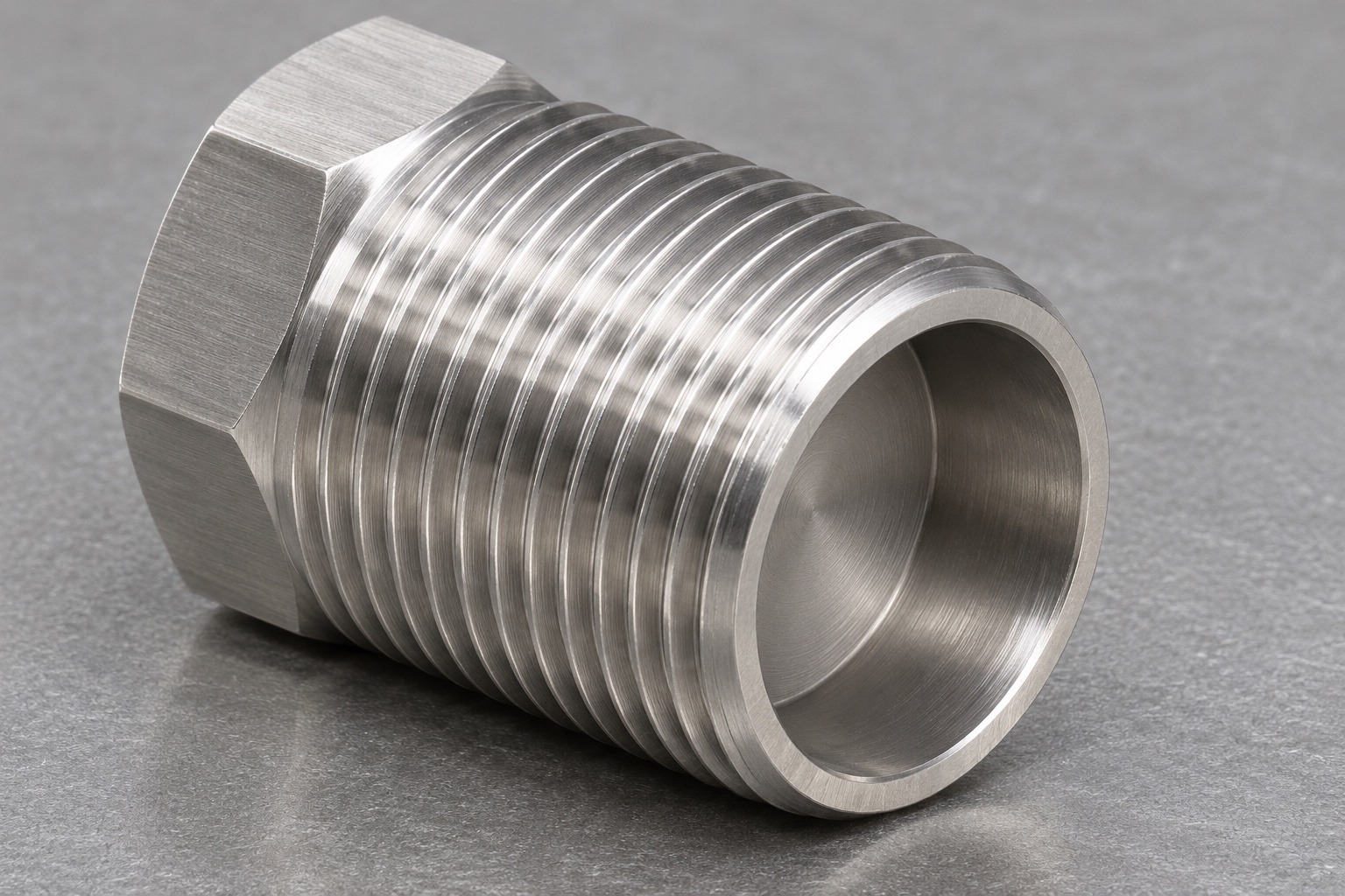
A spring-loaded device may contain a threaded housing, a spring, a moving contact and a retention arrangement. This guide addresses only a conceptual machined housing body for an internal medical equipment mechanism. The illustrated 316L stainless steel component has an externally threaded cylindrical wall, a hexagonal rear wrench head and a smooth axial blind cavity opening at the opposite end. The rear end is closed. No spring, ball, pin, cap or retention feature is included. The component must not be described as a complete functioning spring plunger simply because its outside resembles one.

Identify the real assembly interfaces before machining
The design review should identify what locates the housing, which surface receives a wrench and how the internal parts would be assembled and retained in the complete mechanism. An open blind cavity alone does not define the retention method. The equipment designer must specify that arrangement separately, together with any necessary design changes. Do not invent an operating stroke or spring force from the cavity depth. The machining drawing should distinguish the housing's accepted dimensions from the additional requirements used to evaluate the assembled spring-loaded device within the equipment.
State the external thread and its seating reference
Specify the external thread designation, handedness, usable engagement length, lead-in and runout condition rather than showing only a nominal outside diameter. The drawing should identify whether the hex head face is a locating seat or merely a wrenching feature. If a mating component governs installation, identify its thread and relevant reference surfaces. A threaded body that enters a hole by hand has not necessarily met every drawing requirement. The permitted seating condition and any assembly fastening procedure belong in controlled documents, not in a general assumption derived from the component's appearance.
Dimension the blind cavity from identified surfaces
A blind cavity requires a clear definition of diameter, depth, bottom geometry and entrance condition. Specify which face is used as the depth reference and whether a flat bottom or a permitted tool shape is intended. The illustrated concept uses a smooth cavity with a solid floor and no internal thread. An axial through hole would be a different geometry. Do not use total body length as a substitute for a cavity-depth measurement. The drawing should also make the remaining rear material and minimum wall requirements reviewable without asking an operator to infer them from a shaded model.
Review the relationship between bore and thread
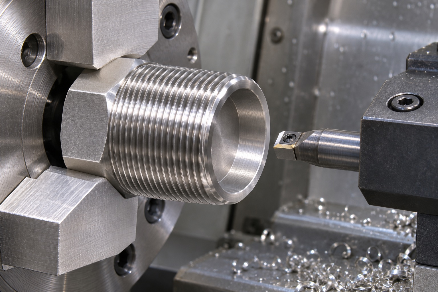
Where the assembly needs a relationship between the external thread axis and internal cavity, the drawing must express it in a measurable way. The manufacturing route should then explain how those features are established and retained through setup changes. Nominally concentric model surfaces do not eliminate the need for an agreed acceptance method. The hexagonal head may provide useful wrench access, but it should not automatically become the only inspection reference. Distinguish the actual functional axis and seating surfaces from convenient external features that happen to be easy to hold in a vise.
Plan stock, support and operation order
For the 316L concept, confirm the specified material condition and documentation before selecting bar stock or a preliminary blank. The sequence would consider how the outside thread, blind cavity and wrench head can be machined with suitable support. Holding an already finished thread in hard jaws may create marks, so the setup plan should identify acceptable contact surfaces or protective tooling. Tool selection, cutting conditions and chip control depend on the real design and machine. No universal process parameter or achieved dimensional capability is established by the illustrative manufacturing photograph accompanying this article.
Manage chips at the closed end of the cavity
The blind floor makes chip removal and access important process-planning questions. Review the tool's available clearance, the method of evacuating chips and any process fluid that could remain at the bottom. A cavity that looks empty at its entrance may still retain a fragment deeper inside. The manufacturing plan should describe the intended intermediate checks and the final compatible cleaning route. Any change made to improve access must preserve the approved geometry. Drilling through the closed rear end for convenience would create a different part and would require design approval rather than an informal shop adjustment.
Choose depth and bore checks that reach the feature
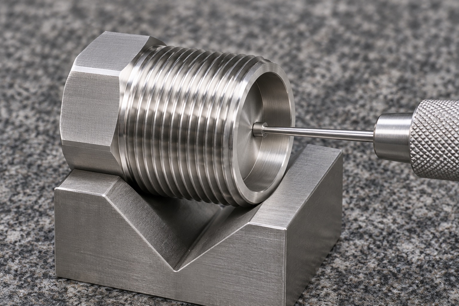
Define the inspection method before production, especially where probe tips or measuring contacts may not reach the intended floor or cylindrical surface. A depth probe must reference the correct face and contact the specified bottom region. Bore size, cavity depth and the relationship to the outside thread may require different methods. Record the instrument and setup conditions relevant to the approved limits. The inspection illustration does not contain a readable number or a measured acceptance result. A photograph of a probe entering a cavity cannot establish the remaining wall thickness or compliance with every drawing requirement.
Keep thread checking separate from complete function
External thread acceptance should use the agreed designation, limits and checking method, with any gauge identified and controlled. A limited installation observation in a mating component can answer an assembly question but should not replace every specified inspection. The body alone cannot demonstrate spring force, plunger travel, retention, fatigue life or safe contact behavior. Those characteristics require the complete controlled assembly and its relevant evaluation. Manufacturer information about commercial spring plungers describes complete products; it does not transfer their performance to an unassembled custom housing shown in an illustrative technical article.
Protect edges while removing process residues
Review the thread start, thread runout, cavity entrance and wrench-head transitions for burrs against the approved edge requirements. Avoid uncontrolled polishing that changes engagement or rounds a locating face. Cleaning should address the blind floor as well as the readily visible outside surfaces, using a procedure compatible with the material and intended use. If passivation or another surface process is requested, identify its specification and evidence separately; the alloy name alone is not proof that such treatment occurred. No sterile condition, particle classification or patient-contact suitability is claimed for the illustrated body.
Keep protective packaging out of the cavity
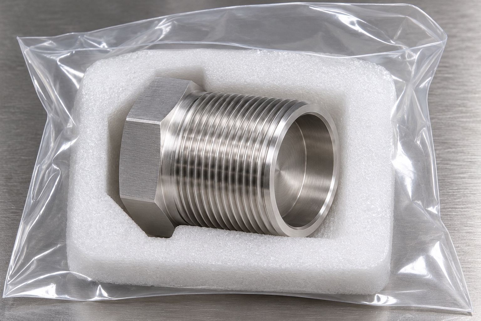
Individual separation can protect the external thread from impact during handling and shipment. Packaging should support the body without pressing a hard object into the bore or leaving loose fibers at the blind floor. Any protective plug must be explicitly agreed and suitable for the cleanliness expectations; a convenient piece of foam should not be pushed into a functional cavity by habit. Identification belongs outside the functional surfaces. A clear bag and fitted pocket describe protective handling only. They do not establish a validated sterile barrier, cleaning qualification or approval of the finished medical equipment.
Request the housing and assembly documents separately
A useful inquiry includes the housing drawing and model revision, quantity, 316L material condition, external thread, cavity geometry, reference scheme, finish and required inspection records. It should also identify the separate assembly design where spring, moving element and retention are relevant to the review. State cleaning, packaging and requested documentation without implying that unprovided certificates already exist. This division lets the supplier quote the machined body while the design owner retains responsibility for unresolved assembly functions. The article's generated images are geometry and process illustrations, not customer delivery evidence or proof of an operating spring plunger.
Manufacturer background reference: www.carrlane.com.
FAQ
Is the illustrated body a complete spring plunger?
No. It is an unassembled housing concept without a spring, moving contact or retention arrangement. It cannot demonstrate force, stroke, retention or safe system operation. A complete device requires its own controlled assembly design and evaluation.
Does the cavity pass through the rear head?
No. The concept has a smooth axial blind cavity and a closed solid rear end. The depth, bottom geometry and remaining material must be defined by the actual drawing. A through hole would be a different approved configuration.
Is the internal cavity threaded?
No internal thread is present in this concept. The machine thread is on the outside cylindrical wall. Any internal thread, separate cap or retention detail would need explicit design information and review rather than being inferred from the illustration.
Can a depth reading establish all wall geometry?
No. A depth observation checks a defined axial feature under an agreed setup. Bore size, outside geometry and relationships may require additional methods. The actual drawing determines how remaining material and other acceptance requirements are assessed and recorded.
Does 316L establish passivation or sterility?
No. Material identity, any specified surface treatment and sterile condition are different requirements. A passivation process needs its own specification and records where requested. Protective packaging and the alloy name do not establish medical-device approval or patient-contact suitability.
What information is needed for a quotation?
Provide the controlled drawing, model, quantity, material condition, external thread, blind-cavity requirements, reference scheme, finish and inspection needs. Add cleaning and packaging expectations and identify any separate assembly documents needed to review retention or moving components.

tanghangyun@oemach.com