
A 0.02 mm flatness tolerance does not automatically mean that a robot mounting base must be ground. A stiff, moderately sized and stress-stable part can often meet the requirement by controlled finish milling.
Grinding becomes more attractive when the contact surface is broad, the material is steel or hardened, the roughness is demanding, or batch consistency must be protected against milling marks and thermal drift.
The correct choice depends on the surface function and inspection condition, not the tolerance value alone.
Finish milling versus grinding for 0.02 mm flatness
| Decision factor | Finish milling is often suitable | Grinding is often preferred |
|---|---|---|
| Material | Aluminum and machinable non-hardened materials | Steel, hardened material or stable grindable stock |
| Surface size and stiffness | Moderate span with adequate thickness and support | Large span, high repeatability or a dedicated finish allowance |
| Surface roughness | Typical machined contact finish where cutter marks are acceptable | Low roughness such as Ra 0.8 or a uniform lay requirement |
| Process risk | Stable datum, low residual stress and controlled unclamped result | Heat treatment, distortion risk or need to correct a pre-machined plane |
| Cost and lead time | Fewer operations and setups | Added setup and cycle justified by function or capability |
First Define What The Surface Does
A rail seat, reducer interface, sealing plane and general support surface do not have the same requirements. Flatness controls the surface itself, while parallelism and perpendicularity describe its relationship to a datum and may be equally important for robot alignment.
Confirm whether acceptance applies in the free state, supported on inspection pads or after specified bolt preload. A thin base can pass while clamped and move after release, or distort during assembly if the support points are inconsistent.
When Finish Milling Can Hold 0.02 mm
Finish milling is a realistic choice when the part is stiff, the area is moderate, the blank has been stress stabilized and the fixture supports the component without bending it. The datum must be established before the final face is cut.
Balanced stock removal, a separate finishing allowance, sharp and stable tooling, controlled coolant and a light final pass help limit heat and deflection. The part should be released and rechecked rather than accepted only in the clamped state.
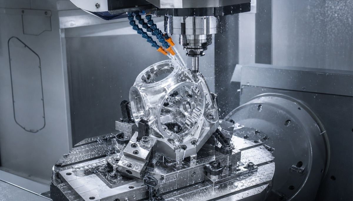
A stable datum, distributed support, controlled clamping and a planned final pass are essential when finish milling must hold a 0.02 mm flatness requirement.
When Grinding Adds Real Value
Grinding is useful for steel or hardened bases, broad contact faces, demanding roughness and repeated lots where a uniform surface pattern is important. It can remove the controlled allowance left after rough machining and heat treatment.
Grinding is not automatically superior for every aluminum base. Wheel loading, heat and handling can create new risks, while a well-controlled milling process may be more direct. The decision should be validated with first-article data and surface function.
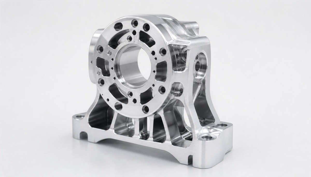
Material, span, wall thickness, surface function and bolted assembly condition determine whether milling alone is sufficient or grinding should follow.
Plan The Route Around Stress And Clamping
A robust route typically establishes a reference, roughs both sides in a balanced sequence, allows stress relaxation or stabilization when needed, semi-finishes the main faces, and then applies the selected final process. Critical holes and rail interfaces should remain related to the final datum.
For thin or open structures, soft jaws, distributed supports, vacuum fixtures or profile supports may reduce local distortion. Clamp force should be repeatable and low enough that the measured free state represents the delivered part.
Inspect Flatness Separately From Other Geometry
Flatness can be measured by CMM, a surface plate with an indicator or a suitable height-measurement system. The method, support condition, temperature and point or scan distribution must match the drawing and acceptance plan.
Do not report flatness as proof of parallelism to the opposite face or perpendicularity to a bore. Those are separate controls and require the relevant datum. Surface roughness should also be measured independently where specified.
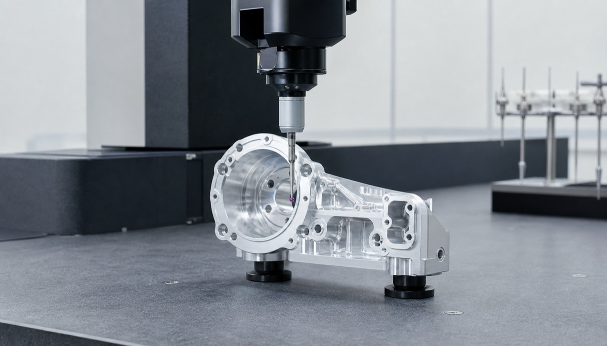
Flatness is evaluated across the specified surface, while parallelism or perpendicularity requires a separate datum relationship.
RFQ Information That Prevents Rework
Provide enough functional information for the supplier to select and quote the finishing route.
- Material grade, temper or hardness and any heat-treatment condition
- Surface dimensions, wall thickness, weight-relief pockets and support locations
- Flatness, parallelism, perpendicularity and roughness requirements
- Free-state, supported-state or bolted-state inspection condition
- Guide rail, reducer, seal or other mating function
- Quantity, first-article report, sampling plan and surface-treatment sequence
Summary
Finish milling can meet 0.02 mm flatness on a stable, adequately supported robot base with moderate area and suitable roughness. Grinding is justified by material, span, surface finish, post-heat correction or repeatability. Define the assembly function and inspection state before selecting either process.
FAQ
Can finish milling reliably achieve 0.02 mm flatness?
Yes, for suitable material, size, stiffness and fixture conditions, but capability must be confirmed on the released part with the agreed inspection method.
Is grinding always more accurate?
No. Grinding can improve flatness consistency and roughness, especially on steel, but it adds setup and can introduce heat or handling risk. Process capability matters more than the process name.
Does 0.02 mm flatness also control parallelism?
No. Flatness has no datum. Parallelism to another face or axis must be specified and inspected separately.
Should the base be measured clamped or free?
The drawing or inspection plan should define the condition. Free-state inspection is common, but some thin assemblies require specified support points or bolt preload to represent use.
Ready to get a quote for your CNC machined parts?
Submit your engineering drawings to qiancj@oemach.com. We support prototype sampling and small-batch production with strict tolerance control.