
Not every dimension on a robot part needs a coordinate measuring machine. CMM time should be reserved for characteristics whose relationship to a datum affects assembly, alignment or motion accuracy.
Locating holes, bearing seats, multi-hole patterns and mating-face geometry are typical priorities. Simple outside sizes, standard threads, edge breaks and visual requirements are often better checked with dedicated gauges or conventional instruments.
The inspection plan should follow part function and the drawing datum system instead of using the CMM as a substitute for every other measurement method.
Which robot-part characteristics should be measured by CMM?
| Characteristic | Recommended method | Why it matters |
|---|---|---|
| Locating and bearing bores | CMM for position, axis relationship and orientation; bore gauge for size | Controls assembly location, bearing alignment and joint motion |
| Multi-hole patterns | CMM from the functional datum reference frame | Verifies true position and clocking across the mounting interface |
| Mating faces | CMM, surface plate or height system according to access and tolerance | Controls flatness, parallelism and perpendicularity to the locating features |
| Simple sizes and threads | Micrometers, calipers, pin gauges and GO/NO-GO gauges | Faster functional acceptance without unnecessary CMM time |
| Burrs, finish and cleanliness | Visual, tactile and dedicated surface checks | These conditions are not fully represented by coordinate data |
Prioritize Features That Define Assembly
A locating bore may be within diameter tolerance but still place the joint incorrectly if its position or axis is wrong. The same applies to bearing seats, dowel holes, reducer interfaces and sensor mounting features.
These characteristics should be measured from the functional datum reference frame shown on the drawing. This lets the report describe the assembled relationship rather than a convenient inspection setup.
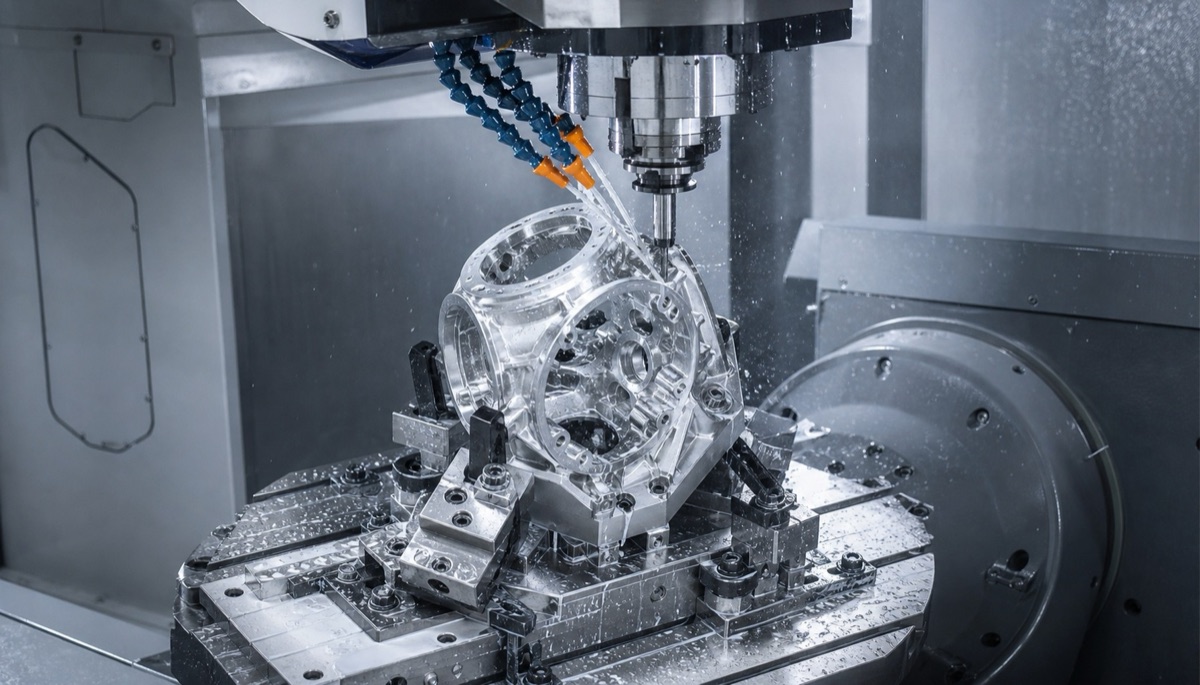
Complex bores, faces and hole patterns often span several orientations, making the final datum relationship more important than any one isolated size.
CMM Is Best For Datum-Related Geometry
True position, coaxial relationships, perpendicularity, parallelism, profile and complex multi-face geometry are strong CMM candidates. A single setup can relate features that would otherwise require several instruments and manual calculations.
The measurement program must still define probe access, point distribution, alignment method and evaluation standard. More points do not automatically produce a better result if the datum simulation is wrong.
Do Not Put Every Dimension On The CMM
Micrometers and bore gauges are often more direct for size. Pin gauges quickly confirm hole limits, thread gauges verify functional acceptance, and optical systems can be efficient for small profiles or edge features.
A CMM also does not replace burr inspection, surface-roughness measurement, coating checks or cleanliness review. The best final inspection plan combines methods according to the failure mode.
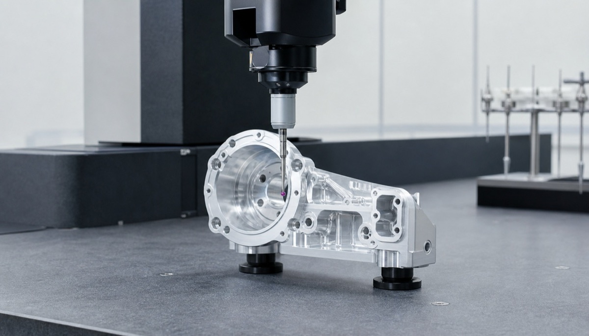
The probe measures locating bores, bearing seats, hole-pattern position and face orientation from the same datum reference frame used on the drawing.
Build A Report That Purchasing Can Audit
A useful report identifies drawing revision, part and batch, measurement equipment, calibration status, datum alignment, nominal value, tolerance, actual result and sampling quantity. Critical features should be traceable to balloon numbers on the drawing.
For prototypes, all agreed critical characteristics are normally checked on the first article. For repeat batches, the sampling plan should reflect feature risk, process capability and any recent engineering or tooling change.
Information To Confirm Before Ordering
Inspection cost and lead time are easier to control when acceptance is defined before quotation.
- Released 2D drawing, 3D model and matching revision
- Functional datum system and list of critical characteristics
- Required report format, ballooned drawing and measurement units
- First-article scope, batch sampling level and retention period
- Mating bearings, dowels, reducers or sensors used for functional checks
- Surface treatment, cleaning and packaging requirements that apply after measurement
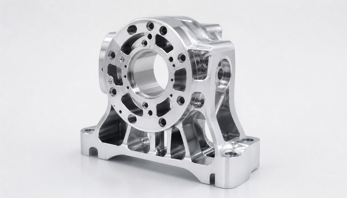
Shipment acceptance should combine CMM results for functional geometry with gauges and visual checks for threads, burrs, finish and cleanliness.
Summary
Use CMM inspection for robot-part features whose position, orientation, form or axis relationship controls assembly and motion. Use dedicated gauges and conventional tools for direct size and functional checks, then combine the results in a traceable report tied to the drawing revision.
FAQ
Must every dimension on a robot part be measured by CMM?
No. Prioritize datum-related functional features and geometry that conventional tools cannot evaluate reliably. Direct sizes and standard threads are often faster with dedicated instruments.
Which features are usually mandatory CMM items?
Critical locating holes, bearing-seat relationships, multi-hole true position, mating-face orientation and complex profiles are common priorities when they control assembly or motion.
What should a CMM report show?
It should identify the drawing revision, datum setup, nominal and tolerance values, actual results, equipment, date, part or batch traceability and sampling quantity.
Can a CMM verify burrs and thread quality?
Not completely. Burrs need visual or tactile checks, and standard threads normally require GO/NO-GO gauges or another specified functional method.
Ready to get a quote for your CNC machined parts?
Submit your engineering drawings to qiancj@oemach.com. We support prototype sampling and small-batch production with strict tolerance control.