
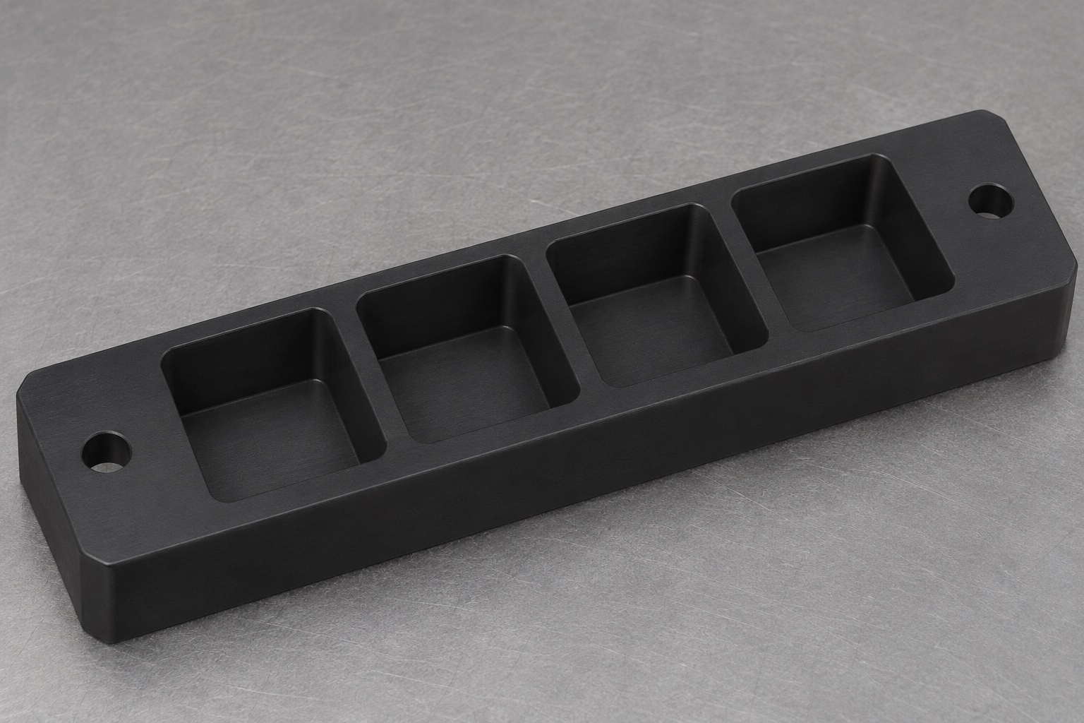
Identify the carrier's limited mechanical role
A medical laboratory analyzer may move or temporarily hold closed sample containers in a machined carrier. This article considers a black POM-C bar with four upward-facing square blind pockets and two plain mounting holes outside the pocket row. It supports only approved external regions of the containers. It is not a cuvette, a reagent manifold or a validated measurement cell. Container geometry, loading sequence and removal access must be supplied by the equipment designer. Naming the part a cuvette transport nest does not establish suitability for patient specimens, a particular assay or an analyzer's complete automated workflow.

Define where the container is allowed to contact
A square outline is insufficient to describe a sensitive container interface. Identify the external support band, bottom contact and regions that must remain free of contact, including any optical windows or identification areas. State whether the nest holds the container during measurement or only during transfer. A pocket that surrounds a window may be unsuitable even when the container fits dimensionally. The mechanical design should also distinguish a locator from a clamp. Do not assume that pocket walls alone provide validated retention during acceleration or that a tight hand fit protects fragile glass.
Resolve internal corners before setting clearances
A milling cutter normally leaves a radius in an internal pocket corner. Compare that radius with the actual container's corner shape and permitted contact zones. An apparently generous square pocket can still interfere at its corners. Specify an approved corner radius or local relief, and examine the remaining walls between neighboring pockets. Do not silently increase every pocket to solve one local interference. A relief that clears the container may affect support or collect debris, so it needs design review. The final drawing should communicate both the usable pocket envelope and the intentionally noncontact regions.
Control depth and vertical support separately
Pocket depth relates the top of the nest to its floor, but it does not automatically define the height of a loaded container. Review the actual bottom geometry, permitted support area and any seating features. State which reference controls the container's vertical position. If a vessel must remain clear of a floor, provide an explicit support concept instead of relying on manufacturing variation. Check that a gripper or manual tool can reach the container at the required stage. The proposed four pockets are blind cavities; drains, windows and other openings would require a separate approved geometry.
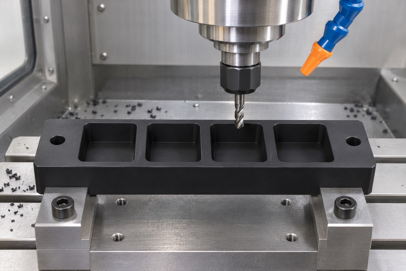
Relate the pocket row to the mounting pattern
Choose a base plane and an agreed origin for the four pockets and the two external mounting holes. Define pitch, row orientation and relevant positional requirements using the equipment interface rather than the stock edge. Consider the total span of the row as well as adjacent-pocket spacing. A cumulative position error can matter to a transfer mechanism even when each pocket width is acceptable. Review screw and tool access with containers present or absent as required. Plain mounting holes do not include metal inserts, threads or special screw seats unless those features are explicitly added to the drawing.
Specify the actual polymer rather than its appearance
Black POM-C identifies a material family and appearance, not every property needed for an application. The purchase definition should name the approved grade, stock form and traceability scope. Ensinger describes POM as a commonly machined engineering plastic; that general background does not qualify a particular black grade for a medical analyzer. Review cleaning exposure, contact restrictions and any regulatory requirements with the responsible design team. Do not infer biological compatibility, sterilization suitability, low particle shedding or chemical resistance to an unspecified reagent from machinability or a clean-looking photograph of the finished carrier.
Plan material removal and support for the pocket walls
The manufacturing discussion should account for the material left beneath each pocket and between adjacent cavities. Tool access, chip evacuation and support can influence whether the finished part matches its released geometry. Review the sequence for the base, pockets and mounting pattern rather than treating each as an independent feature. Avoid excessive clamping that temporarily distorts the bar. The exact cutting conditions and any intermediate conditioning depend on the grade, blank and geometry. Do not copy metal-machining assumptions or promise a universal plastics tolerance without considering the actual final inspection and service conditions.
Agree the inspection environment and part condition
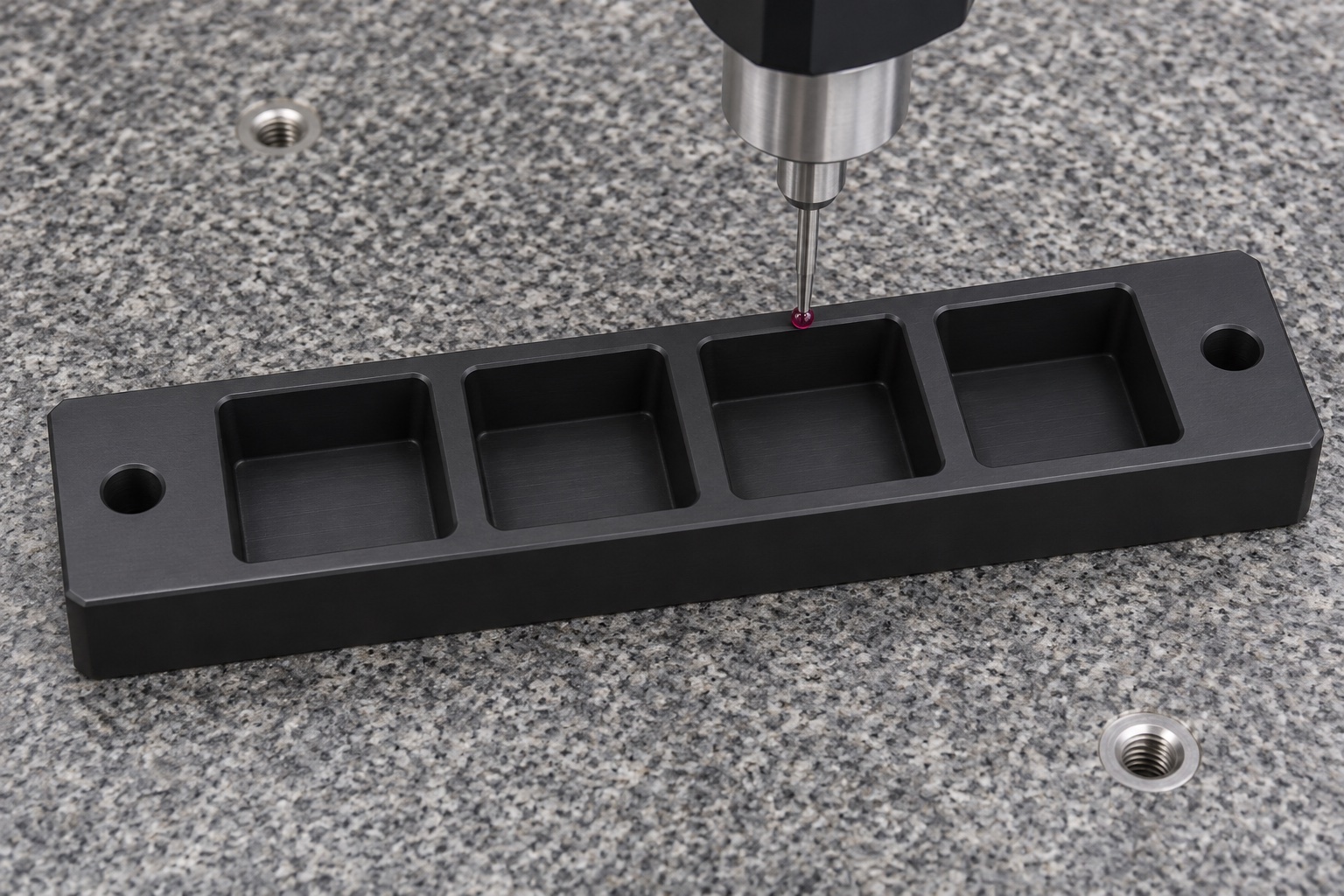
A polymer carrier should be assessed in an agreed condition that permits meaningful comparison with its requirements. Record relevant temperature or conditioning instructions where specified, the support arrangement and the time or process stage of inspection. Choose a method that can reach the blind-pocket floors and corner regions without distorting the walls. Inspect the relationship of the pocket row to the mounting references, not just one opening. A probe or caliper can miss localized interference if the sampling plan is inadequate. The drawing and inspection plan should identify the characteristics that actually govern the container interface.
Finish edges without widening the controlled pockets
Remove burrs or attached material at pocket entries and mounting holes using an approved edge-treatment instruction. The loading edge may need a defined lead-in, but an arbitrary chamfer can remove a needed support band. Do not scrape a pocket until a sample container fits and then report the original dimensions as unchanged. Inspect any approved rework and maintain its traceability. Cleaning should remove machining debris according to the contracted scope. A smooth appearance is not a particle-count result, and protective handling is not evidence of validated decontamination, sterility or compatibility with biological samples.
Separate a handling trial from analyzer performance
An agreed trial may observe loading, seating, orientation and removal using identified empty or otherwise approved nonclinical containers. Record container and gripper revisions and the observation procedure. Successful motion does not demonstrate sample integrity, optical accuracy, assay repeatability, contamination control or safe operation with patient material. Even retention during motion requires conditions relevant to the real equipment. If insertion resistance changes, review corner contacts, debris and material condition before altering the pocket. A carrier modified during development should remain distinct from released production until the documentation and inspection basis have been updated.
Protect the pockets and preserve identification
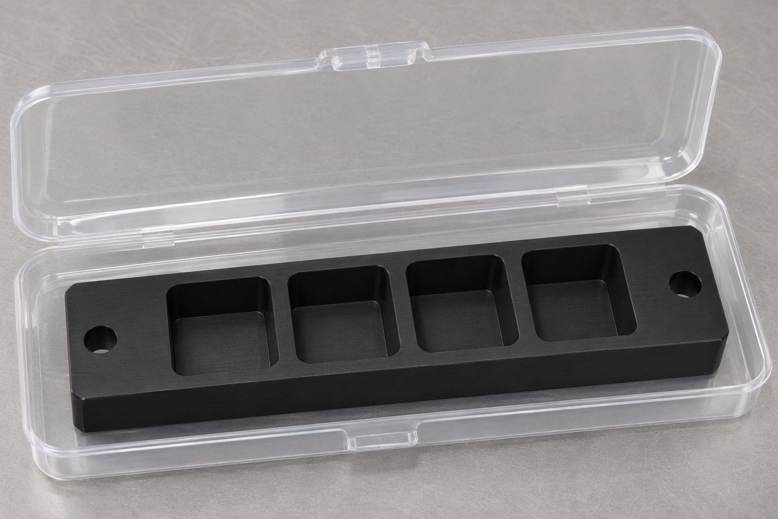
Package the nest so that separators do not force the pocket walls outward or place debris inside the cavities. Protect the mounting face and avoid stacking finished carriers directly against their pocket edges. Keep the part number, revision, material identity and inspection status associated with the component. Any cleaning or packaging material restrictions belong in the order. Ordinary protective trays are not sterile delivery systems. If the purchaser performs final cleaning or assembly, define the handover condition and responsibility. Reusing a container for a fit check should not introduce clinical material into an ordinary machining inspection area.
Prepare a container-specific manufacturing request
Include the carrier drawing and model, container envelope and permitted contact map, pocket-floor definition, corner requirements, row reference system and mounting details. Identify whether the carrier is used during transport, parking or measurement. State the polymer grade, inspection condition, cleaning scope and packaging requirements. Resolve missing retention and handling features before treating the nest as an approved analyzer component. A useful supplier response should distinguish manufacturing capability from any unverified application claims. Dimensional inspection can document the machined part, while container compatibility and the full medical laboratory workflow require their own engineering and validation decisions.
Manufacturer background reference: www.ensingerplastics.com.
FAQ
Does the carrier contact the sample liquid?
Not in this scope. The nest supports approved exterior regions of closed containers. Any direct contact with liquid, reagents or biological samples would change the material, cleaning and application assessment and would require an explicitly revised design and qualification scope.
Why do square-pocket corner radii matter?
A container can interfere at a rounded internal corner even if its side dimensions appear smaller than the opening. Compare actual corner shapes and permitted contacts, then define a radius or relief. Do not solve one corner conflict by silently enlarging all controlled pocket surfaces.
Can one standard pocket fit every cuvette?
No. External dimensions, corners, bottom shape, optical windows and loading arrangements differ. Use the identified container revision and permitted contact map. A nominal category name does not establish a shared mechanical interface or make an unspecified container safe to transport.
Are the blind pockets drainable?
The concept includes no drain or fluid-management feature. A drain, open window or cleaning access feature would need a design change and review of the remaining material and support. Do not infer drainability or validated cleanability from an upward-facing pocket.
Does a smooth POM-C surface prove cleanliness?
No. Surface appearance is not a measurement of particles, contamination or extractables. Define any required cleaning and inspection protocol separately. The material grade and intended exposure also require review rather than assuming a generally machinable polymer is suitable for a medical application.
What can a development handling trial establish?
It can record limited observations under its stated procedure, such as access and seating with identified containers. It does not by itself establish retention in service, assay performance, sample integrity or analyzer qualification. Keep trial observations separate from dimensional acceptance and system validation.

tanghangyun@oemach.com