
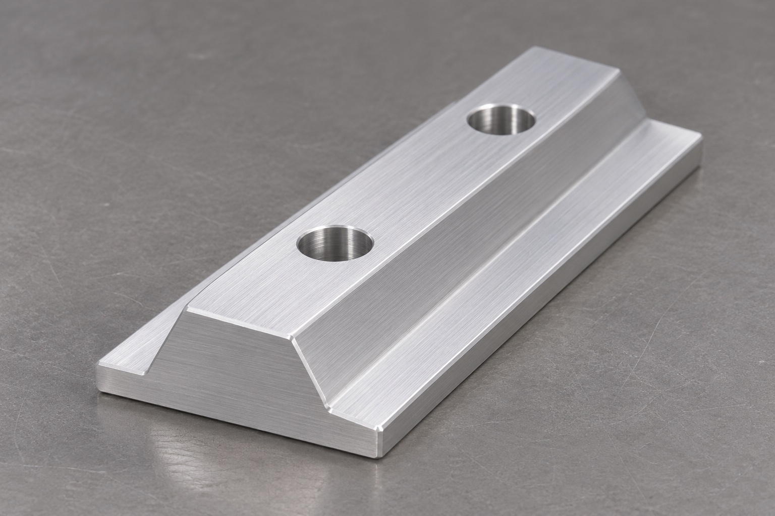
Define the rail before choosing its manufacturing route
A medical analyzer may use a short locating rail to position a removable internal mechanical module. The concept considered here has a wide flat base, a raised trapezoidal ridge that becomes narrower toward its top, and two plain mounting holes. Its sloping sides can provide defined contacts when the mating arrangement is designed accordingly. This is not an undercut dovetail and does not inherently capture a carriage against lifting. Before requesting a quotation, identify the actual positioning function, retention method, removal direction and clearances. A photograph alone cannot establish any of those assembly requirements.

Separate positioning from retention
A locating surface establishes a reference; another feature may be needed to retain the module. Identify which directions the rail is intended to constrain and which surfaces are deliberately relieved. A screw, spring or separate clamp must not be assumed to exist simply because the component is called a rail. Show the supported module and its installation envelope in the manufacturing review. If the assembly must resist vibration or accidental withdrawal, those are system requirements for the designer to evaluate separately. An accepted rail drawing does not by itself demonstrate a secure medical equipment assembly.
Make the trapezoidal section unambiguous
Define ridge height, upper width, lower width and sloping-face orientation in a controlled section view. State the drawing convention for angles so that a flank angle is not mistaken for an included angle. Identify any straightness, symmetry or profile requirements that are actually necessary. Do not apply tight values to every surface without explaining the interface. The broad base is wider than the raised ridge, but the ridge itself narrows upward. If the intended design instead requires an undercut, revise the documents rather than calling this geometry a dovetail and expecting the supplier to infer the change.
Choose usable mounting references
Select the base contact plane and an agreed longitudinal reference before defining the hole pattern. The two plain holes should be related to the functional section rather than an arbitrary stock edge. Specify whether screw heads bear on the rail top, a separate washer or another component. If their seats require counterbores or countersinks, add those features explicitly; the illustrative concept contains plain holes only. Check screw and tool access with the module installed or removed, as appropriate. A hole that is dimensionally correct can still be unusable when the assembly blocks the tightening tool.
Specify the material and delivered condition
Request the exact 6061 grade, temper and stock form required by the approved design. A silver-colored photograph cannot identify an alloy or prove material traceability. Agree whether the rail is delivered machined, anodized or otherwise treated, and which surfaces are included. A treatment can change the final interface dimensions and should be part of the tolerance review. Do not infer corrosion performance or suitability for a cleaning agent from the alloy name. Keep procurement requirements specific to the mechanical component and leave device-level compatibility decisions with the responsible equipment designer.
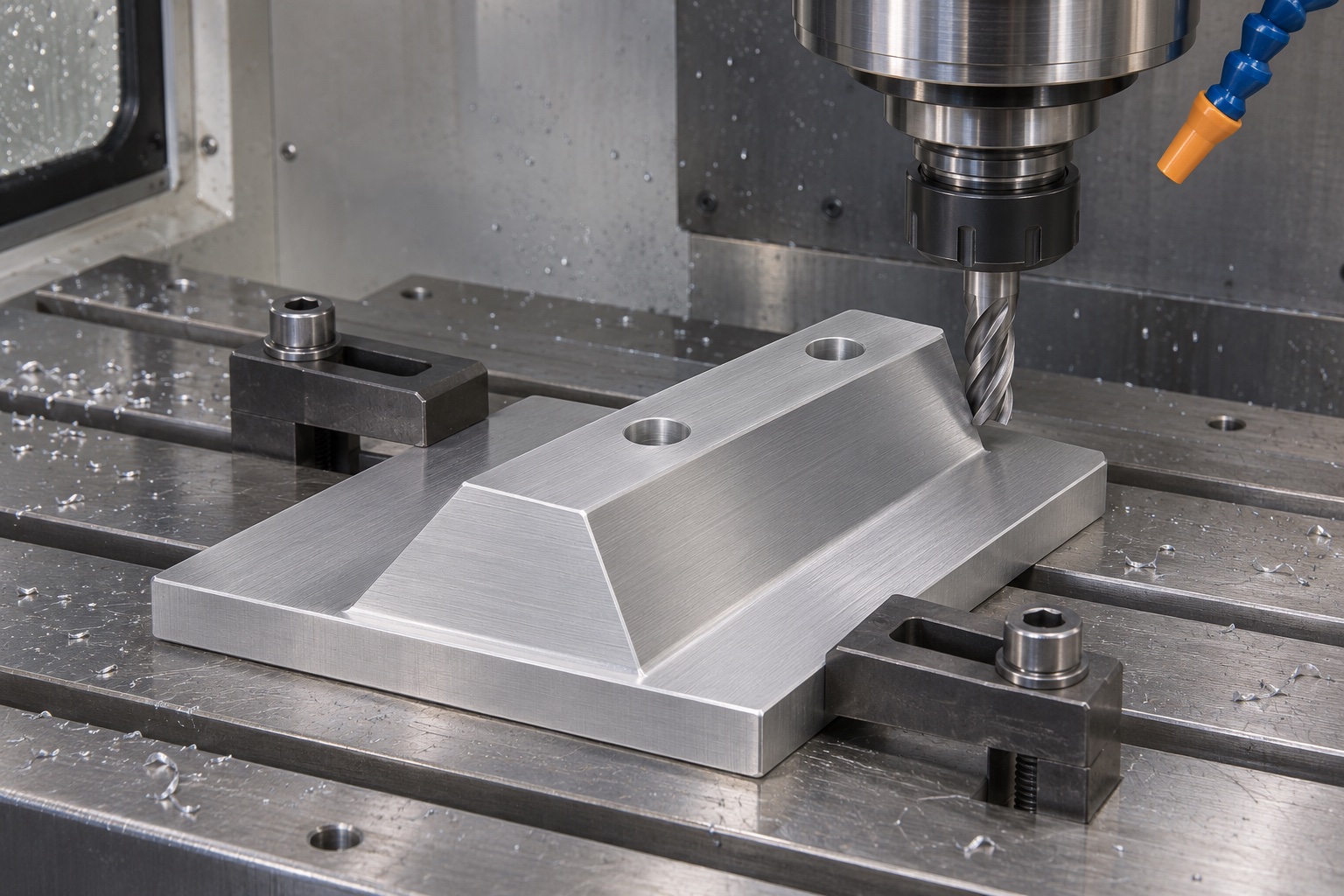
Plan workholding around the contact faces
The machining proposal should explain how the base, ridge and mounting pattern remain related through the necessary setups. Broad support beneath the blank can help avoid treating a clamped shape as the final accepted geometry. Leave access for the selected cutter without damaging already finished contacts. Carr Lane's locating and clamping guidance provides general fixture-design context, not a validated process for this particular rail. Actual fixture forces, stock allowance and sequence depend on the approved dimensions and machine. Inspect the delivered state after release from manufacturing workholding rather than reporting only an in-fixture reading.
Control the transition between ridge and base
The junction between an angled face and the base may contain a cutter radius. Identify whether that transition is a contact, a relief or a clearance zone. A mating sharp corner can interfere with an apparently correct rail if the drawing leaves this relationship unresolved. Use a section or detail to communicate the permitted geometry. Do not remove the radius by uncontrolled hand finishing or silently change the mate to obtain assembly. Where a relief is necessary, agree its extent and the remaining section before machining. Preserve enough surrounding material for the approved mechanical function.
Inspect relationships rather than isolated widths
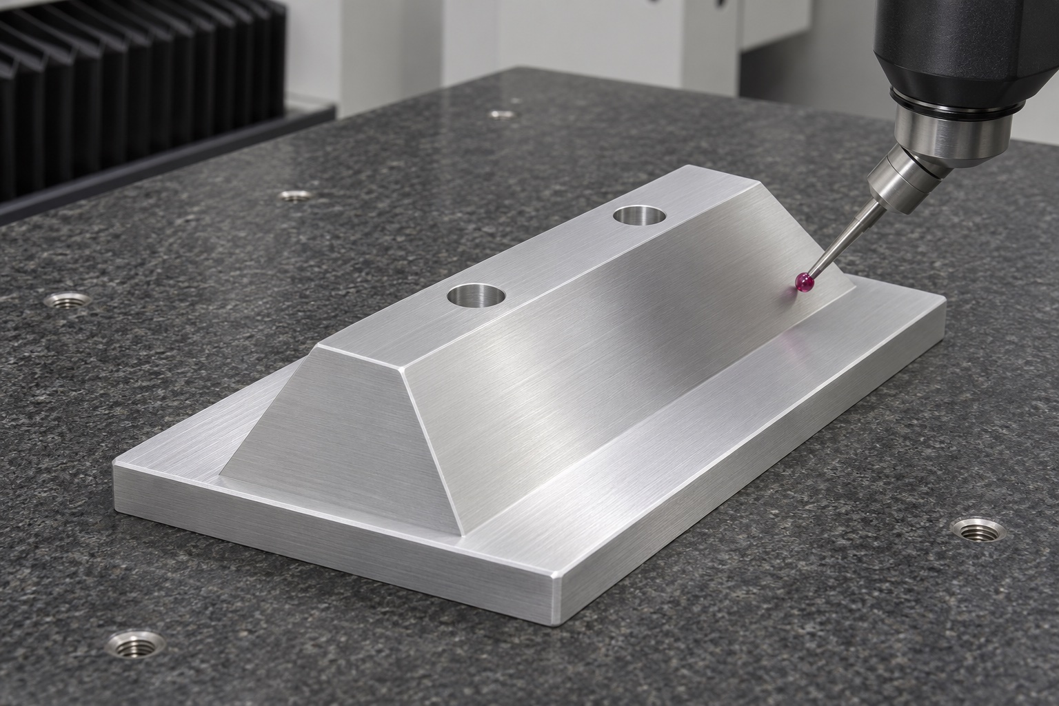
An inspection plan should connect the base plane, the sloping faces and the hole locations to the same reference system. Depending on access and drawing requirements, a coordinate measuring machine, an optical method or suitable contact instruments may be proposed. Record which regions are sampled and how the part is supported. A single caliper width cannot establish the entire angled profile or the position of a hole relative to it. State whether inspection occurs before or after the specified surface treatment. The report should identify the actual drawing characteristics and not substitute a visually neat component for measurement evidence.
Deburr without changing the seating geometry
Define edge breaks where a module is inserted, where screws pass and where an operator might touch the rail during service. Remove attached burrs without rolling a functional sloping edge into a rounded seating surface. Separate cosmetic brushing from the finishing of specified contacts. If an anodizing mask or handling fixture marks a working surface, the acceptance decision should follow the drawing rather than an informal appearance preference. Cleaning is also a contracted process with defined scope. A clean-looking metal rail is not evidence of measured particle cleanliness, validated disinfection, biological suitability or sterile delivery.
Keep an assembly observation within its scope
An agreed trial can observe insertion, screw access, orientation and contact with identified mating components. Record their revisions and the condition of the rail. A successful manual installation does not establish repeatability, alignment stability, retention force, vibration resistance or service life. These require a relevant system-level evaluation. If the module rocks or binds, review references and unexpected contacts before polishing the sloping faces. Any approved dimensional change belongs in revised manufacturing documents. A modified sample should not become an undocumented master that quietly replaces the engineering definition for later production.
Protect the rail during handling and shipment
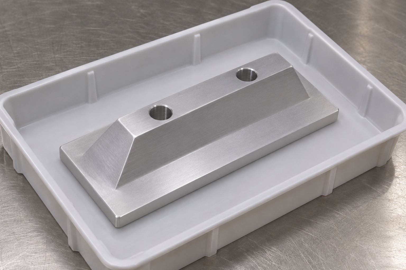
Provide individual protection for the angled contacts, base and hole entries so that neighboring parts do not strike them. Packaging should also allow the part number, revision and inspection status to remain identifiable. Specify any material restrictions or cleanliness requirements before the supplier chooses trays or sleeves. Ordinary protective packaging is not sterile packaging. If the component is later cleaned or assembled by another supplier, identify the handover condition and responsibilities. Do not assume that a protective film can contact every finished surface without review, particularly where adhesive residue would affect the intended assembly process.
Prepare a rail-specific request for quotation
A useful request includes the controlled model and drawing, mating contact concept, material condition, surface treatment, mounting details, inspection references and packaging scope. Highlight the distinction between a narrowing trapezoidal ridge and an undercut retaining profile. State which documents govern if the model and drawing differ, and resolve the disagreement before release. Request evidence for the characteristics that matter rather than a generic promise of precision. This approach supports a meaningful CNC manufacturing discussion while keeping dimensional acceptance, optional assembly observations and medical equipment qualification as separate decisions with identifiable owners.
Manufacturer background reference: www.carrlane.com.
FAQ
Is this locating rail a dovetail slide?
No. The illustrated ridge narrows toward the top and has no retaining undercut. It may locate a mating module through approved contacts, but it does not inherently prevent lifting. A captured slide requires its own geometry, retention concept and engineering review.
What information is needed to quote the angled faces?
Provide a controlled section, dimensions, angle convention, reference system, required form or orientation controls and delivered surface condition. Include the mating contact concept. A perspective photograph and an overall width do not define how the module should seat.
Can the mounting holes be changed to countersinks?
Only after the screw interface and remaining material have been reviewed and the documents revised. The example uses plain through holes. A countersink or counterbore changes the seat geometry and must not be added merely because a particular screw is available.
Does a correct profile prove positioning repeatability?
No. Dimensional inspection documents the specified rail geometry. Repeatability depends on the complete mating arrangement, retention, installation procedure, surface condition and relevant operating environment. Establish a separate evaluation if that result is required for the equipment.
Should the contact faces be inspected after treatment?
The acceptance condition should match the approved drawing and purchase requirements. If treatment is included in the supplied part, review its effect on the interfaces and state which characteristics must be assessed in the final condition rather than assuming unfinished measurements are sufficient.
Can the rail be supplied in sterile packaging?
Sterile delivery is not included in this illustrative manufacturing scope. Specify any cleaning, packaging and validation requirements separately. An individually protected rail and a clean visual appearance do not establish sterility or suitability for a particular medical device.

tanghangyun@oemach.com