
A LiDAR scanning mirror mount sits at the intersection of the optical path and a rotating mechanism. A correct bore diameter alone does not guarantee that the mirror surface will remain square and concentric to the rotation axis.
The mount, shaft, bearings and mirror attachment should therefore be reviewed as one rotating assembly. Face runout, journal roundness, coaxiality, fit, preload and balance all influence scan repeatability.
Critical controls for a scanning mirror mount and rotor shaft
| Feature | Engineering concern | Process and verification |
|---|---|---|
| Mirror mounting face | Flatness, perpendicularity and face runout to the shaft axis | Finish the face and center bore from a common datum; inspect on a representative axis |
| Rotor shaft journals | Roundness, coaxiality, diameter and surface finish | Precision turn, stabilize and grind when the bearing and speed requirement justify it |
| Bearing fits | Clearance or interference, temperature rise and preload | Specify fit by function; record actual journal and bore measurements by batch |
| Assembled rotor | Radial runout, face runout, vibration and balance | Recheck after assembly under defined support, preload and speed conditions |
Build One Optical And Rotational Datum Chain
The mirror mounting face determines the optical attitude, while the center bore, bearing seats and shaft journals define rotation. Their relationship matters more than any single size on the drawing.
A useful datum scheme starts from the bearing or shaft axis, relates the mirror seat to that axis, and defines angular clocking where the optical design needs it. Inspection should reproduce the same logic.
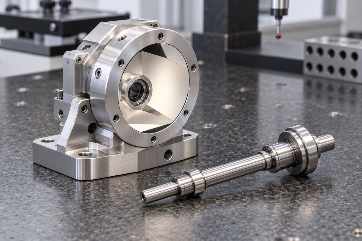
The optical mounting face, center bore, bearing journals and shaft axis must form one functional datum chain rather than a group of isolated dimensions.
The Mirror Mount Needs More Than A Bore Tolerance
The bore can pass its size limit while the face is tilted, warped or eccentric. That condition makes the mirror describe a cone during rotation and changes the outgoing beam angle from cycle to cycle.
Flatness, face-to-axis perpendicularity, concentricity or position, and face runout should be assigned according to the optical error budget. Clamping and mirror bonding or pressing must not distort the seating face.
Machine The Shaft For Bearing Function
Journal diameter determines the bearing fit, but roundness, coaxiality and surface texture determine how smoothly the rotor runs. Shoulders also need controlled squareness because they locate bearings and spacers axially.
Precision turning may be sufficient for moderate requirements. High-speed or low-runout journals often need staged turning, stress stabilization and cylindrical grinding, followed by measurement between appropriate centers or datums.
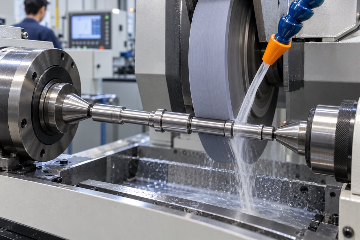
Grinding may be required when bearing-journal roundness, coaxiality, surface finish and runout cannot be achieved reliably by turning alone.
Bearing Fit And Temperature Must Be Reviewed Together
A fit that is correct at room temperature can change with shaft, housing and bearing temperature. Excessive interference raises preload and heat; excessive clearance reduces support stiffness and can increase vibration.
The drawing should define the bearing type, shaft and housing fits, surface requirements and assembly method. Actual mating dimensions should be recorded for prototypes and critical batches so drift is visible before assembly.
Inspect Before And After Assembly
Individual inspection covers the mirror face, center bore, bearing seats, shaft journals, shoulders, roundness, coaxiality and surface finish. Runout is checked using the functional axis rather than a convenient nonfunctional diameter.
After bearings, shaft and mirror holder are assembled, radial and face runout are measured again under defined preload. If operating speed makes mass distribution important, dynamic balance and vibration acceptance should be specified separately from dimensional inspection.
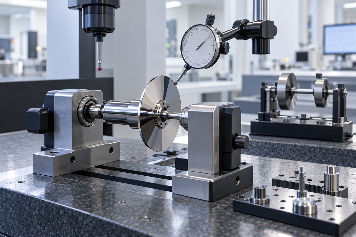
Assembly-level verification connects individual part geometry with the actual rotating condition; dynamic balance is evaluated at the specified speed range when required.
Information To Send With An RFQ
The supplier needs the optical, rotational and assembly conditions that determine the process route and inspection cost.
- Mirror attachment method, seating boundary and allowable mounting distortion
- Operating speed range, bearing type, preload and dynamic balance requirement
- Journal, bore, face runout, coaxiality, roundness and roughness limits
- Material, heat treatment, surface finish and stray-light control
- Assembly-state inspection, vibration test and batch traceability format
Summary
LiDAR mirror mounts and rotor shafts must be controlled as one optical rotating system. Stable scanning depends on the common datum relationship among the mirror face, center bore, bearing seats and journals, followed by assembly-level runout and balance verification where required.
FAQ
Why is the mirror-mount bore diameter not enough?
The face can still be tilted or eccentric to the rotation axis. Perpendicularity, coaxiality and face runout determine the mirror attitude during rotation.
Does every rotating mirror shaft require grinding?
No. It depends on speed, bearing fit, surface finish and runout limits. Grinding is evaluated when precision turning cannot provide reliable margin.
What is the difference between runout and dynamic balance?
Runout describes geometric motion relative to an axis. Dynamic balance addresses mass distribution and vibration at speed; one can pass while the other fails.
Should inspection be repeated after assembly?
Yes when bearing preload, press fits, adhesive curing or clamping can change geometry. Assembly-level measurement reveals the condition used in operation.
Ready to get a quote for your CNC machined parts?
Submit your engineering drawings to qiancj@oemach.com. We support prototype sampling and small-batch production with strict tolerance control.