
Define the mechanical guide function
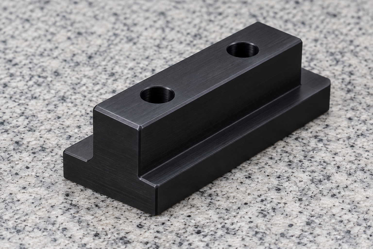
A service-position guide inside a medical laboratory instrument may use a machined polymer slider to connect a moving accessory to a controlled rail interface. The illustrated concept is a one-piece black POM-C block with a wide flat shoe, a narrower centered raised stem and two plain vertical through holes. Its constant section resembles an inverted T. No rail, screw, insert or locking device is shown. This is not a threaded T-nut, a qualified bearing or an independent restraint. The designer must define guiding contacts, installation route, allowed movement and separate retention before the supplier selects a manufacturing plan.

Identify the complete rail interface
Obtain the controlled slider drawing and model, rail section, end access, adjacent structure and actual instrument revision. Specify which vertical faces guide the stem and which shoulder or bottom regions contact or clear the rail. A nominal slot opening does not define the complete mating section. Review rail variation and final surface condition together with the slider. Do not assume that a familiar T-shaped profile matches any commercial extrusion. The required contacts and clearance must follow the real assembly, rather than a photograph, a convenient rail offcut or an external width checked in isolation.
Review end loading and service removal
A wide shoe below a narrower rail opening may require insertion from an accessible end or another specifically designed installation route. Define that route before machining the component. Record obstructions, stops, surrounding cables, fastener access and the intended order of assembly and removal. Do not infer drop-in installation or permission to flex the polymer from the isolated image. Cutting a temporary slot, forcing the shoe through a mouth or removing a shoulder is a design change. Resolve missing access with the equipment team instead of allowing an improvised installation method to become an undocumented production requirement.
Separate stem width from shoulder clearance
Specify stem width, shoe width, shoulder height, useful lengths and their required geometric relationships. Identify the surfaces that set lateral position and those that provide vertical clearance. An acceptable overall width alone does not establish both interfaces. Review clearance over the full permitted travel, including joints or end conditions in the real rail. Do not reduce a guiding face until one sample slides easily without controlled authorization. A dimensional definition should make clear whether a proposal changes guidance, support or clearance rather than treating every outer surface as interchangeable cosmetic stock.
Define the two plain mounting holes
Specify hole size, depth through the component, spacing, location and approved entry treatment. The actual mounting arrangement must identify screws or other hardware, mating component, seating surfaces and separate retention. The plain holes do not provide a thread, calibrated position or an independent lock. Review tool access and whether a fastener end can interfere with the guide path. Do not add threaded inserts, counterbores or a hidden nut because they seem convenient. Such decisions affect wall sections and contacts and belong in controlled documents before the part is machined and inspected.
Specify the exact black POM-C material
Identify the approved copolymer acetal grade, stock form, condition, lot evidence and purchased final processes. Black appearance does not make POM-C, POM-H, filled polymers and other materials interchangeable. Ensinger's POM machining information provides general material-processing context and distinguishes material variants; it does not approve this custom slider or qualify a medical instrument. Material identity alone does not establish low friction, wear life, cleaning compatibility, electrical safety or sterility of a finished installation. Define relevant requirements and supporting evidence for the actual grade, geometry and environment rather than transfer a generic material description into a device claim.
Plan machining around related guiding faces
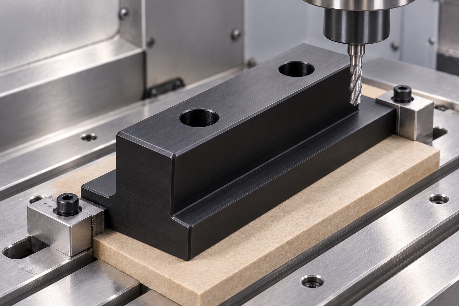
Relate bottom, shoulders, stem sides and holes through the holding and repositioning sequence. Review tool reach and support for the narrow stem before choosing contact pressure. Protect useful faces from embedded chips or concentrated restraint. Intermediate observations may assist process development, but final inspection must address the agreed finished condition rather than the shape imposed by a fixture. Any conditioning or intermediate treatment needs a material-specific approved route. No universal cutting speed, clamp force or achieved clearance is prescribed. A flat shoe or straight side visible only under restraint is not a complete acceptance result.
Finish transitions without informal fitting
Inspect hole mouths, shoulder intersections, ends and outer edges for attached material or unwanted sharp features. Apply approved edge requirements without reducing useful guide lengths or changing the defined section. Polishing until a slider runs in one unidentified rail can hide a geometry disagreement and needs design authorization. Cleaning should match the purchased scope and preserve grade identity. A smooth black surface does not demonstrate measured particles, low friction, validated disinfection or sterile delivery. Agree any marking location outside useful contacts and distinguish identification from an unsupported claim that the part is qualified for a medical operating environment.
Inspect the full mating section
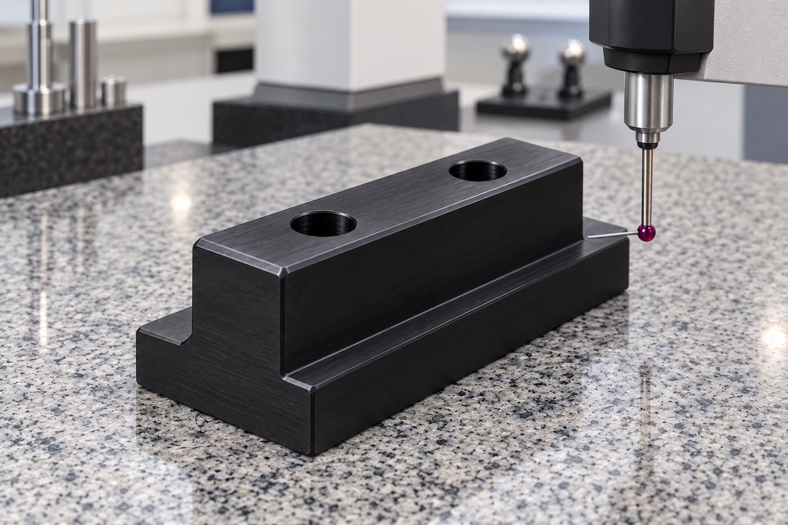
Map stem and shoe widths, shoulder height, thickness, straight guiding faces, hole pattern and required relationships to accessible methods. Agree support, measuring contact and final condition before acceptance. One caliper reading cannot establish all guide contacts or their relation to both holes. If a region cannot be reached, determine an appropriate method rather than accept the component solely because it slides in a sample rail. A real report should identify revision, material lot, numbered characteristics, methods and actual observations. The inspection image depicts a possible setup, not an achieved fit, clearance or measured travel performance.
Limit optional rail-travel observations
A separately agreed trial can examine insertion, seating, intended travel, hardware clearance and removal with identified slider, rail and accessory revisions. Record orientation, assembly sequence and any separate stop or retention arrangement. Smooth manual motion does not establish load capacity, friction, wear life, particle generation, vibration behavior or operating retention. These require separately defined evaluation of the complete actual installation. Distinguish trial parts from released production. Unexpected binding should prompt interface review before scraping a shoulder, changing a hole or substituting another rail just to obtain a favorable movement demonstration.
Protect guide faces and variant identity
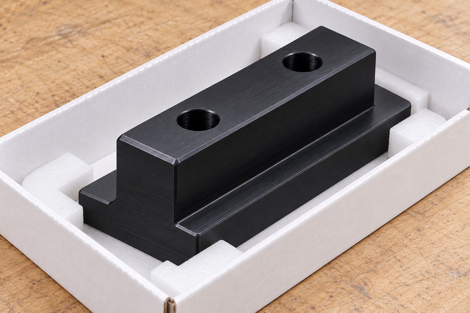
Separate finished sliders so neighboring parts and loose hardware cannot strike the stem, shoulders or hole entries. Use supports that do not bend the shoe or leave pressure marks on useful guiding faces. Maintain grade, lot, revision, process and inspection status with dispatch. Ordinary mechanical packaging does not mean sterile supply. Receiving checks should distinguish similar sliders with different shoulder heights, shoe widths or hole patterns before installation. Keep the component linked to its approved rail variant while leaving the complete instrument's travel, retention and application qualification within separately controlled procedures and evidence.
Prepare a rail-specific manufacturing inquiry
Provide controlled slider geometry, the complete mating rail section, intended contacts and clearance, travel envelope, installation route, hardware, stops, exact material, final processes and inspection deliverables. Separate an optional fitting observation from motion and wear qualification. Review rail, accessory, cleaning-scope or assembly changes before another order. Approved adjustments must enter revised documents rather than remain in a hand-scraped slider used as a universal master. This creates a traceable polymer-machining project without inventing service-life results or confusing dimensional acceptance of a T-shaped component with a qualified medical-equipment guidance or safety system.
Manufacturer background reference: www.ensingerplastics.com.
FAQ
Is the slider a threaded T-nut?
No. The concept has two plain through holes and no thread or insert. Actual fasteners and retention belong to separately controlled assembly documents. A T-shaped exterior alone does not define a clamping nut, locking function or a compatible commercial rail interface.
Can the part be inserted through any T-slot opening?
Not automatically. A wide shoe under a narrower opening may require access from an end or another approved installation route. Review rail section, obstructions and assembly order. Do not force the polymer through the opening or remove a shoulder without authorized changes.
Does overall width verify the whole guide fit?
No. Stem, shoe, shoulder height, useful contacts and their relationships are distinct requirements. The controlled drawing and inspection plan must address them in the agreed finished state. A caliper reading or easy travel in one sample rail is not a complete dimensional report.
Does POM-C identity prove low friction or wear life?
No application result is established here. The exact grade, finished geometry, mating rail, conditions and required performance need separate definition and evidence. Material naming and smooth manual movement do not qualify friction, wear, particles or suitability of the entire medical instrument.
Can the shoulders be scraped until travel is easy?
Only through an authorized change and relevant revised inspection. First review the actual rail, contacts, clearances and support condition. A hand-fitted sample must not silently replace the approved geometry or become the next production master for different rails.
What should a repeat order review?
Review rail and accessory revisions, installation access, guide contacts, shoulder height, hole pattern, stops, retention, exact grade and final processing. Incorporate approved adjustments into controlled documents rather than a modified sample or motion assumptions taken from another equipment installation.

tanghangyun@oemach.com