
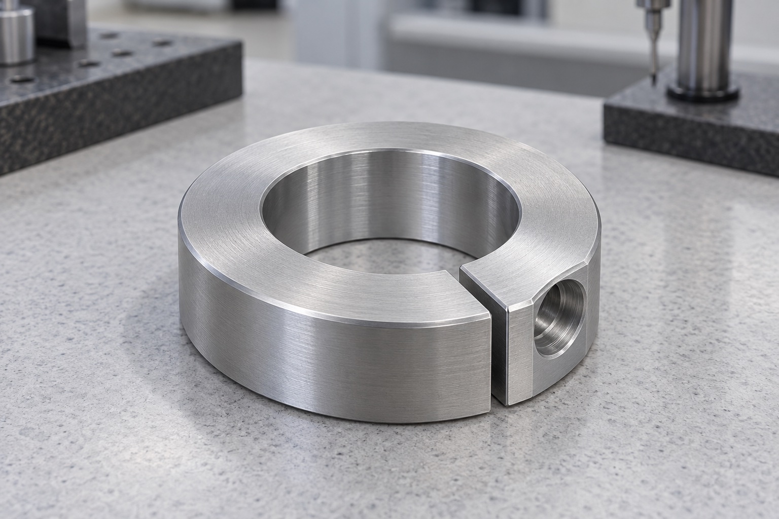
Define the collar within the actual equipment
A service-adjustment shaft in a medical laboratory instrument may need a separately designed collar to establish a mechanical position. The illustrated concept is a one-piece 6061 aluminum ring with a smooth central through bore, one radial slit and a tangential screw interface across that slit. No screw, shaft or surrounding mechanism is supplied by the image. This is not a two-piece collar, a calibrated stop or an independently qualified safety restraint. The equipment designer must identify the intended contact, adjustment, retention and access before a supplier can define manufacturing and inspection. A familiar circular silhouette does not complete those requirements.

Identify the shaft and assembly sequence
Obtain the controlled collar drawing and model, actual shaft specification, adjacent components and instrument revision. Establish which shaft region enters the bore, how the collar reaches its location and whether nearby shoulders prevent installation. An apparently convenient nominal diameter is not a complete interface. Record permitted orientation and screw-tool access in the assembled instrument, including removal during service. Do not assume that a one-piece ring can pass an existing shoulder simply because its slit is visible. Any proposed opening, deformation or alternative installation method requires design approval rather than an undocumented shop-floor workaround.
Specify the bore and its inspection state
Define bore size, useful length, relevant form and relationships to the contact faces. State whether dimensions apply to the unassembled, unclamped part or to another explicitly controlled condition. The slit means external restraint or a fitted screw can change the observed geometry; an inspection plan must therefore identify support and any applied assembly condition. A shaft that passes through one sample does not verify every bore characteristic. Do not accept a distorted ring merely because a fixture or measuring contact makes it look circular. Keep a component dimensional result distinct from an installed gripping or sliding observation.
Control the slit as a manufactured feature
Specify slit width, location, orientation, end boundaries and allowed edge treatment relative to the bore and screw features. Review access for cutting and removing attached material without altering the useful bore. The pictured opening is not an approved gap value or a measurement. Do not close the split by force to simplify inspection or widen it to fit an unidentified shaft. A revised slit can change the remaining sections and the assembly response. Resolve drawing and model conflicts before finish machining, and retain authorized changes in the controlled geometry rather than a hand-modified master sample.
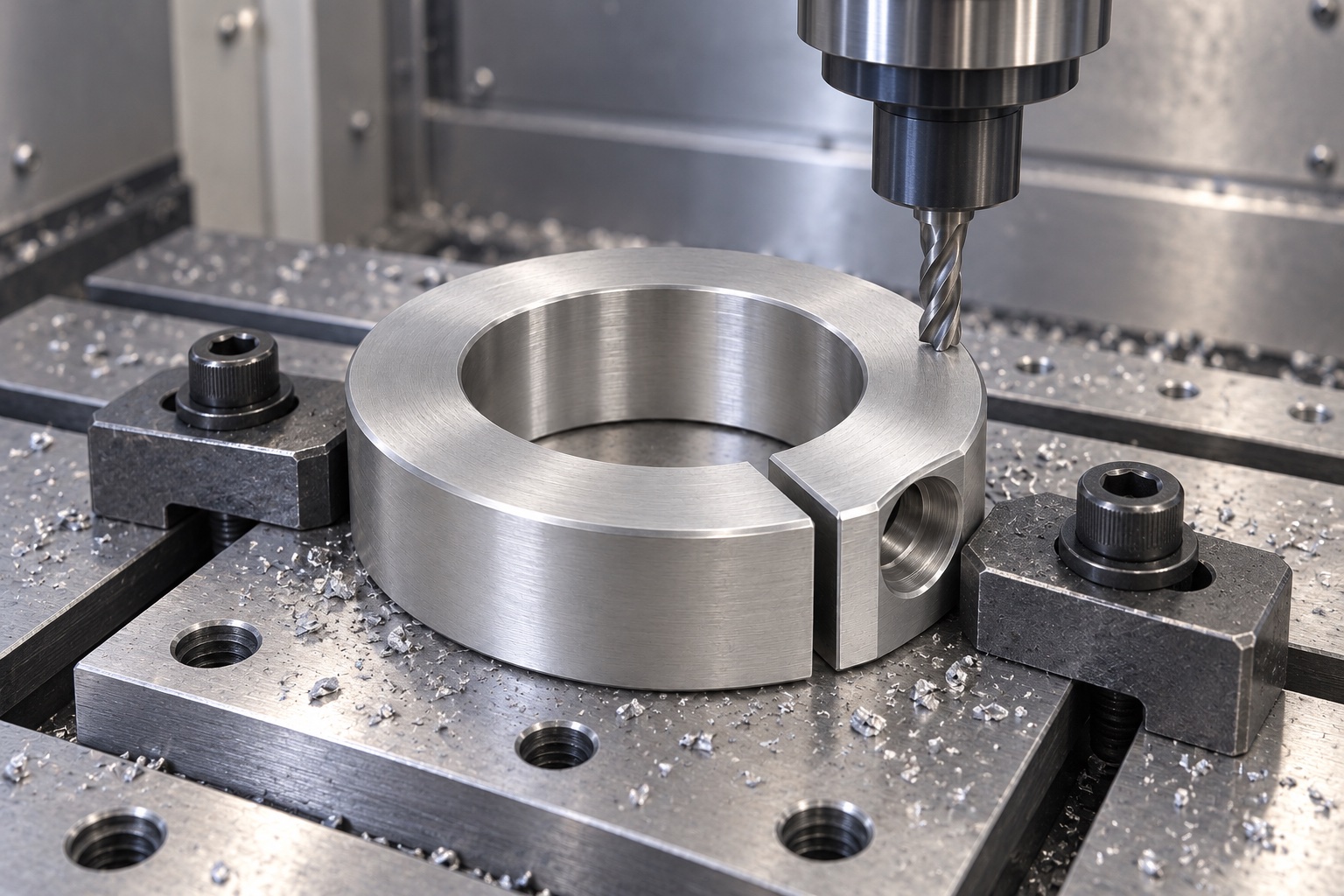
Define the complete screw interface
The real drawing must distinguish the screw clearance, head seat, mating thread, engagement and tool approach on the two sides of the slit. Identify the exact fastener and its separately approved assembly procedure. A circular port in a rendering does not establish thread identity, depth or a tightening value. Check tool access after installation, not only while the ring is isolated on a bench. Do not add a hidden nut, insert, locking treatment or different screw to complete an ambiguous design. Those choices affect the real assembly and require agreement before manufacturing a repeatable component.
Keep material and finish identity explicit
State the approved 6061 stock condition, form, lot evidence and purchased final treatment. A silver surface does not identify an anodized or untreated condition. Review processes affecting the bore, slit edges, screw seat and thread, and identify which checks concern the final supplied state. Preserve material identity through turning, milling and packing. A material record identifies stock within its scope; it does not establish holding force, vibration resistance, biological compatibility, cleaning validation or sterility. A commercial collar's rating cannot be transferred to this custom design merely because both components use aluminum and a split ring.
Plan supports without concealing deformation
Relate the turning references, bore, faces, slit and tangential operations through the actual machining sequence. Review the remaining wall and screw regions before choosing holding contacts. Carr Lane's engineering resources provide general locating and clamping background, not an approved fixture recipe for this collar. Remove chips before repositioning and protect useful contacts. Intermediate observations can guide process development, but final acceptance must address the agreed finished condition. No universal clamp force, cutting parameter or achieved tolerance is specified here. A ring constrained into shape by its manufacturing fixture should not become the acceptance standard.
Finish edges without changing the interface
Inspect bore entries, both slit boundaries, outer edges and screw-seat transitions for attached material or unwanted sharp features. Apply the approved edge definition while preserving bore length, thread function and the specified slit. Hand polishing until a shaft fits can hide a dimensional disagreement and requires authorized review. Cleaning should follow the purchased scope and preserve traceability. A smooth bright surface does not prove low particles, validated disinfection or sterile delivery. Where identification is required, agree a location that does not compromise the useful contact or introduce an unapproved geometric feature.
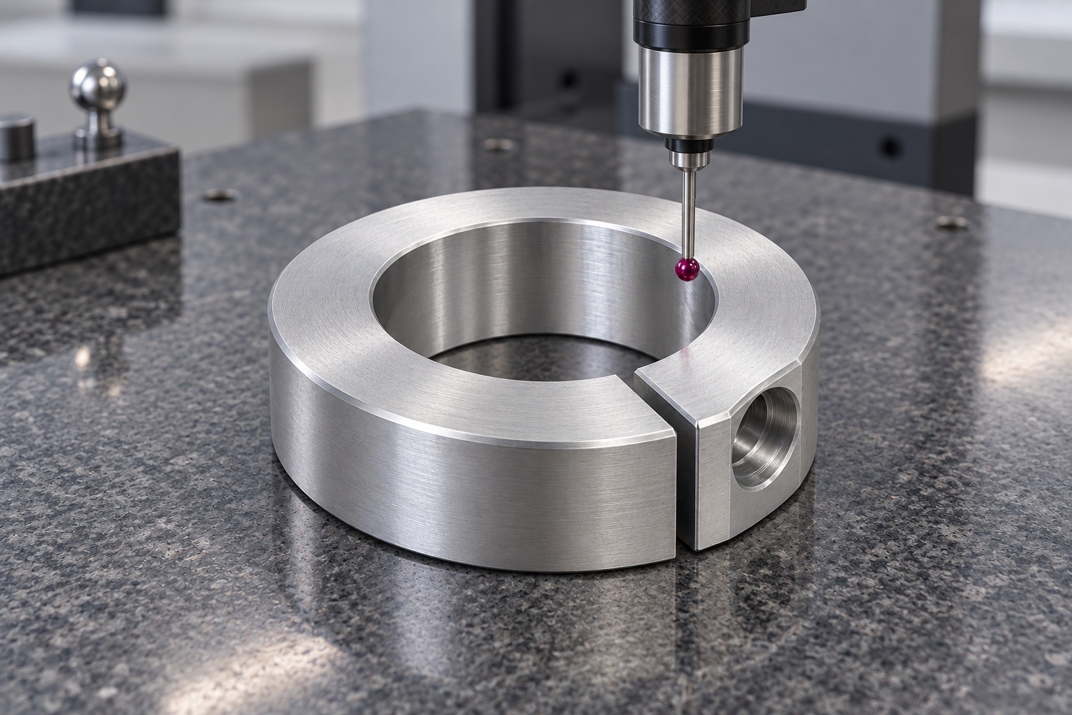
Inspect related features in an agreed condition
Map bore, faces, outside envelope, slit and screw features to accessible inspection methods. Record the support arrangement and any required assembly condition before acceptance. A single bore gauge or a screw entering the thread does not verify the full geometry. Restricted probe access should trigger method review, not omission of a characteristic. A real report should identify revision, material lot, numbered requirements, methods and actual observations. The illustrative measuring-machine image shows a possible setup only; it supplies no achieved tolerance, measured grip or validated relationship between the component and the instrument's operating position.
Bound any optional assembly observation
A separately agreed trial can observe installation, orientation, screw access and seating using identified collar, shaft and hardware revisions. Record the assembly procedure and the actual condition of the test. Easy installation or apparent manual resistance does not establish holding force, slip resistance, vibration behavior, fatigue life or safe restraint. Those require separately defined evaluation of the complete real mechanism and intended conditions. Distinguish trial pieces from released production. Unexpected contact or movement should be reviewed before changing the slit, bore or screw, rather than modifying one sample to obtain a favorable demonstration.
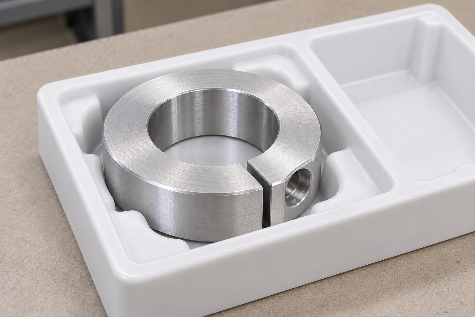
Protect the split and contact surfaces in transit
Separate finished collars so loose hardware and adjacent components cannot strike the bore, slit edges or screw seat. Choose supports that do not force the gap closed or bend the ring during transport. Keep grade, lot, revision, final-process and inspection status with the shipment. Ordinary mechanical protective packaging is not sterile supply. Receiving checks should distinguish similar collars with different bores, gaps, threads or widths before assembly. Preserve the approved variant identity while leaving shaft retention, tightening control and the instrument's application qualification within their own documented responsibilities.
Prepare a collar-specific manufacturing inquiry
Include controlled geometry, shaft and screw identity, useful contacts, installation route, tool access, free-state or other inspection condition, material, final processes and inspection deliverables. Separate optional fitting from clamp-performance qualification. Review changes to shaft finish, screw, surrounding mechanism or assembly procedure before repeating manufacture. Incorporate approved prototype adjustments into revised documents rather than a polished or forcibly opened ring used as a production master. This defines a traceable CNC supply project without inventing holding results or treating an accepted aluminum component as a universally qualified positioning or safety system for medical equipment.
Manufacturer background reference: www.carrlane.com.
FAQ
Is this a one-piece or a two-piece collar?
The concept is a one-piece ring with one radial slit. It is not illustrated as two separable halves. The actual installation route must account for shaft shoulders and neighboring parts; opening the slit by force is not an approved universal assembly method.
Why must the drawing define an inspection condition?
Support, measuring contact or installed hardware can influence a split component's observed geometry. Identify the agreed unassembled state or other controlled condition and use suitable methods. A ring appearing correct while forced in a fixture does not establish the required final condition.
Does the screw-port image establish thread size or torque?
No. The real specification must identify the fastener, clearance, head seat, thread and engagement. Any tightening procedure belongs to the separately approved assembly definition. A rendered circular opening provides neither a thread inspection result nor a safe tightening value.
Does a passing shaft demonstrate holding capacity?
No. It is a limited fit observation with identified parts. Holding force, slip, vibration and operating restraint require separate evaluation of the actual assembled mechanism. Neither dimensional acceptance nor a favorable hand trial supplies those performance results.
Can the bore or slit be adjusted by hand?
Only through an authorized change with revised geometry and relevant inspection. Do not use polishing or forced gap adjustment as an undocumented substitute for the drawing. Preserve the agreed relationship between the bore, slit, screw interface and final inspection condition.
What should a repeat order review?
Review shaft, screw, contact faces, bore, slit, inspection state, material and final treatment together. Check installation and tool access if the surrounding instrument changed. Approved adjustments belong in controlled revisions, not in a deformed sample or a commercial collar's copied rating.

tanghangyun@oemach.com