
Define an equipment-side cable contact sleeve
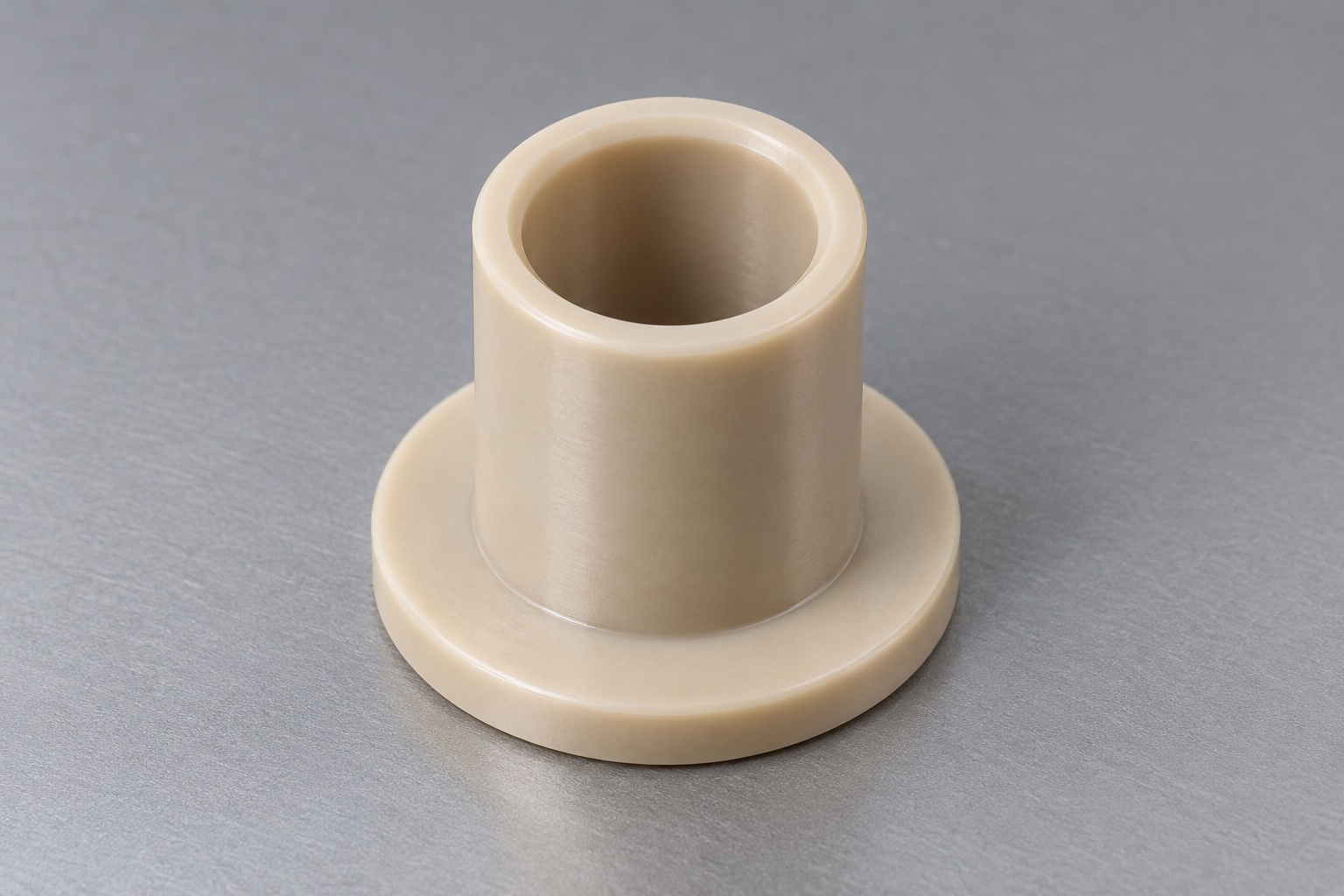
A stationary cable crossing an internal panel of a medical laboratory instrument may use a machined sleeve to provide a defined mechanical contact boundary. The illustrated concept is a one-piece natural unfilled PEEK component with a short cylindrical shank, wider round flange and one smooth coaxial through bore. It has no thread, slit, separate seal or additional hole. It is not presented as a pressure fitting, fluid path, strain-relief device or certified electrical insulator. No actual cable assembly or measured result is shown. The responsible designer must define panel, cable, assembly order and separate retention requirements before manufacture.

Identify the complete cable and panel envelope
Obtain the controlled sleeve drawing and model, panel opening and thickness, cable specification, connector envelope and actual device revision. A nominal cable diameter alone is not a complete interface definition. Identify jackets, labels, boots, joints and any features that may pass through or approach the bore. Review installation and removal with the actual assembly order. Do not assume that a cable already terminated with a larger connector can pass through the finished sleeve. Resolve missing access requirements before machining rather than enlarging the bore informally or using an unidentified cable sample as a universal manufacturing reference.
Specify bore size and entry geometry together
Define useful bore length, size, form and the approved entry and exit treatment. The mouth should be distinguished from the cylindrical contact region. A large chamfer is not automatically an acceptable solution to every cable access problem because it changes contact length and remaining material. Identify the permitted cable-contact band and any relevant clearance in the actual design. A pin fitting one entrance cannot verify the complete bore or both transitions. Do not infer a numerical bend limit, wear life or absence of jacket damage from a smooth-looking rendering of the sleeve.
Relate shank and flange to the panel
State the cylindrical mounting geometry, flange dimensions, useful face and their required relationships. Identify whether the panel opening provides clearance or another approved fit, and specify the finished panel condition. A flange can define a seating boundary without establishing independent retention in every direction. Do not assume a press fit, nut, adhesive, retaining ring or sealing element from the illustration. The equipment documents should define the actual mounting method. Panel geometry, sleeve dimensions and assembly variation must be reviewed together instead of accepting a convenient nominal match or an apparently flush contact in one trial.
Keep cable support distinct from strain relief
The actual instrument must identify how cable motion, routing, access and any separate clamping are controlled. A plain sleeve does not independently demonstrate pull resistance, axial retention, electrical separation, ingress protection or safe cable handling during service. Any additional hardware or procedure belongs to the complete assembly definition and separate application evaluation. Do not create a hidden slit or gripping feature to make an ambiguous concept appear complete. Review cable movement and nearby edges using the actual instrument configuration, and keep dimensional component acceptance separate from qualification of the cable installation and its intended operating conditions.
Select the exact natural PEEK grade
Specify approved unfilled PEEK grade, stock form, condition, lot evidence and final processing. Natural appearance does not make reinforced, filled, medical-designated or other PEEK variants interchangeable. Ensinger's PEEK machining information describes a range of material variants and general processing background; it does not approve this sleeve or transfer a finished-device qualification. Material identity alone does not establish electrical safety, biological compatibility, disinfection performance or sterile status. Define any relevant property and evidence for the actual finished component and environment instead of copying a stock-material rating or assuming that the polymer name completes the medical equipment specification.
Preserve references during turning and bore finishing
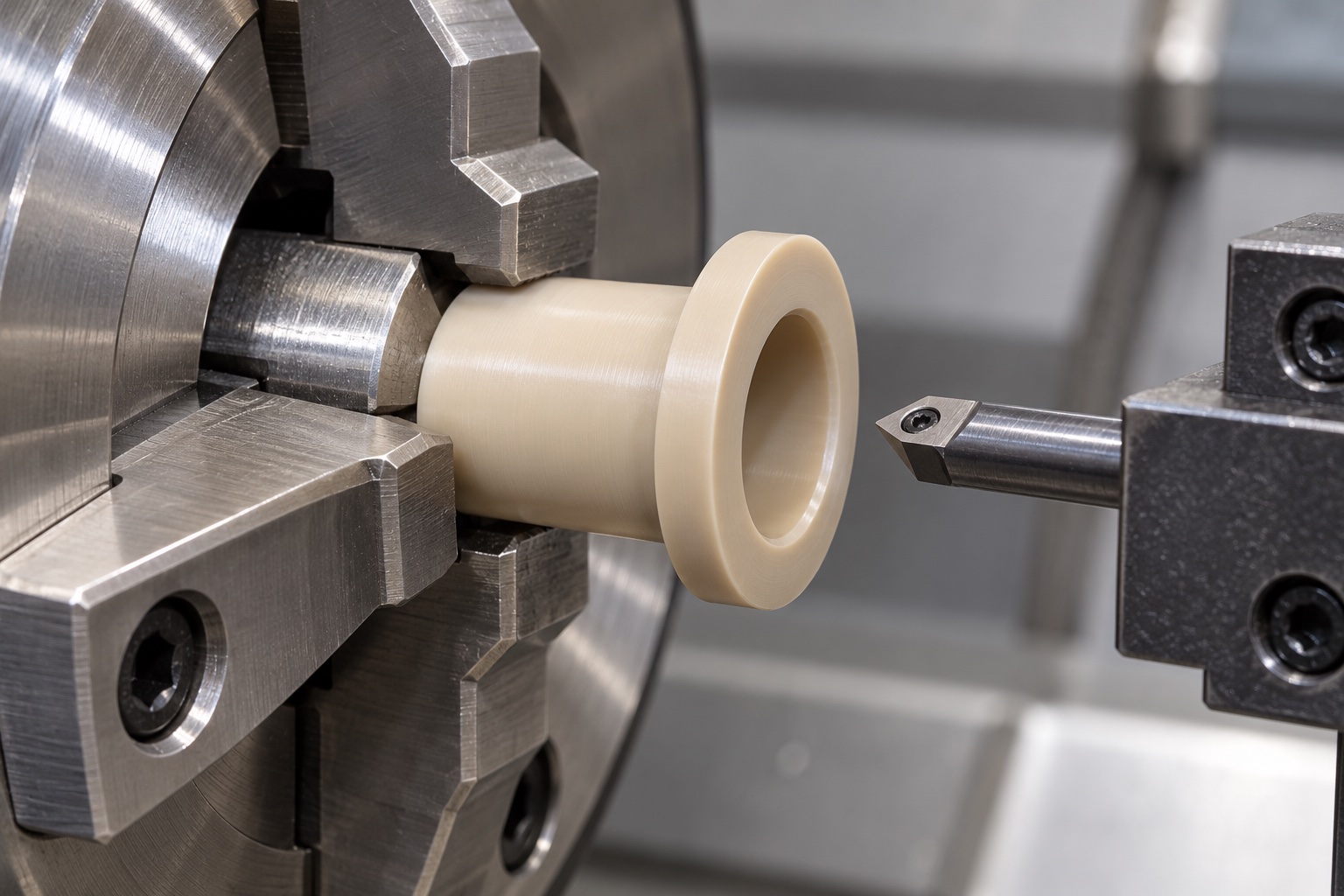
Plan the relation between shank, flange face and bore throughout holding, reorientation and final processing. Protect useful contacts from concentrated pressure and embedded chips. Review tool access, wall sections and the support needed near the flange. A fixture-distorted bore or flange should not be accepted merely because it appears correct while clamped. Intermediate observations may guide process development, but the final inspection must address the agreed delivered condition. Any conditioning or intermediate treatment belongs to a material-specific approved route. No universal tool settings, clamp force or achieved tolerance are prescribed for every PEEK sleeve.
Finish contact boundaries without undocumented resizing
Inspect both bore mouths, flange edges, shank ends and transitions for attached material or unwanted sharp features. Apply approved edge requirements while retaining useful bore length and mounting contacts. Hand polishing until one connector passes can alter controlled geometry and requires authorization. Cleaning should follow the purchased scope and preserve grade identity. A smooth pale surface does not demonstrate low particles, low friction, validated disinfection or sterile delivery. If approved identification is required, agree a location outside useful contact and keep marking separate from a claim that the sleeve provides a certified electrical or environmental function.
Inspect the whole finished interface
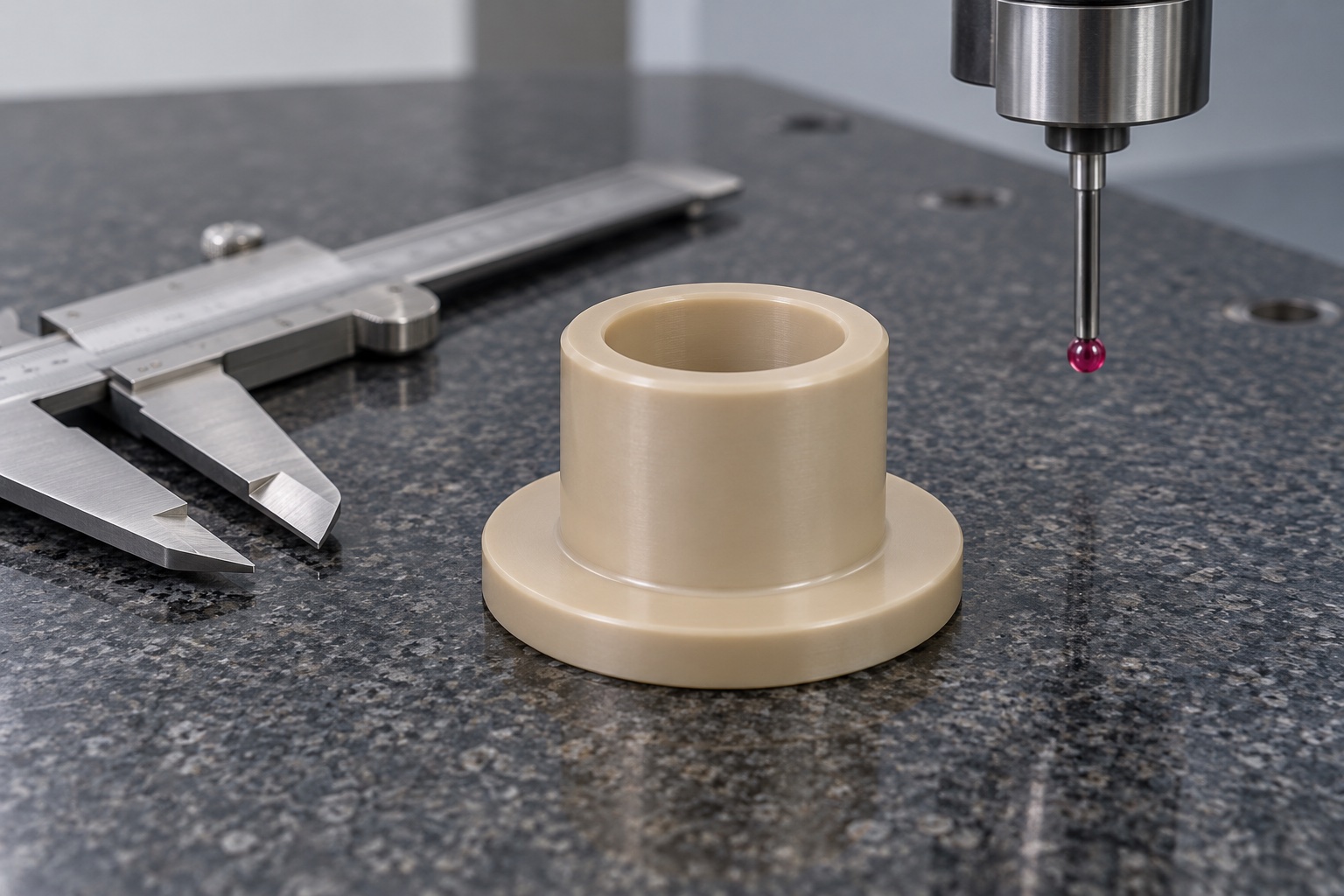
Map bore, entries, shank, flange, useful face and required geometric relationships to accessible methods. Agree support, references, contact pressure and final condition before acceptance. A caliper measuring exterior size cannot verify every region of the bore or its relationship to the mounting surface. If probe access is limited, establish a suitable method rather than accept the part only because a cable passes through. A real report should identify revision, material lot, numbered features and actual observations. A CMM or bore-check photograph illustrates a possible method, not an achieved tolerance or validated cable-contact result.
Bound optional routing and installation observations
A separately agreed trial may examine cable entry, connector access, panel seating and intended routing with identified sleeve, cable, panel and hardware revisions. Record assembly order, orientation and the actual retaining arrangement. Favorable static fitting does not establish strain relief, jacket protection under repeated motion, electrical safety or resistance to ingress. Those require separately defined evaluation of the complete actual installation. Trial pieces should remain distinct from accepted production. Unexpected contact should trigger review before opening the bore, trimming the flange or substituting another cable simply to obtain an easy installation photograph or informal production gauge.
Protect mouths, flange and variant identity
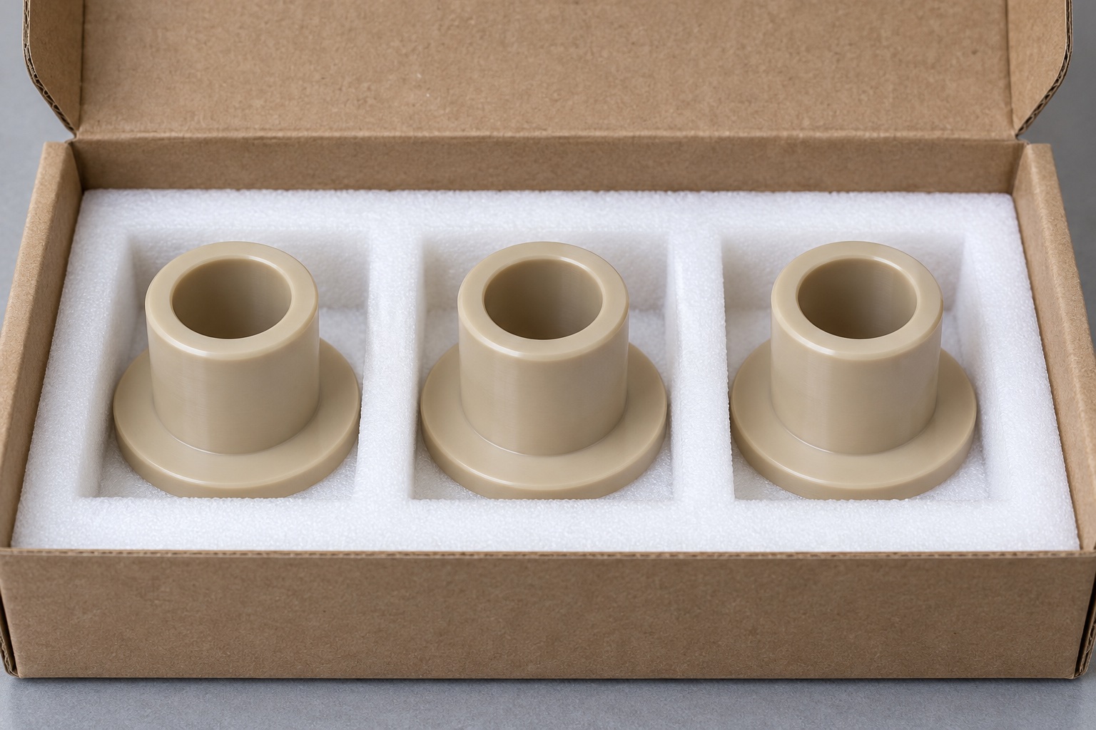
Separate finished sleeves so adjacent parts and loose hardware cannot strike useful bore entries, shanks or flange contacts. Choose pockets and supports that avoid deforming the mounting or cable-contact geometry. Keep grade, lot, revision, final process and inspection status with shipment. Mechanical protective packaging does not imply sterile supply. Receiving checks should distinguish similar sleeves with different bores, wall sections, flange thicknesses or shank lengths before installation. Maintain the link to the actual approved drawing and cable variant while leaving the equipment team's independent routing, retention and application qualification to its own controlled procedures and evidence.
Provide a cable-specific manufacturing inquiry
Include controlled sleeve geometry, panel specification, cable and connector envelopes, permitted contacts, assembly order, mounting and retention, grade, final condition and inspection deliverables. Identify optional fitting separately from cable handling, electrical and full-device qualification. Review changed cables, connectors, panels, cleaning scope or installation methods before repeating manufacture. Approved prototype adjustments must enter revised documents, not remain in a polished sleeve used as a universal master. This defines a traceable PEEK machining project without inventing measured cable protection or confusing one accepted mechanical contact component with a fully qualified medical equipment cable entry or certified electrical safety system.
Manufacturer background reference: www.ensingerplastics.com.
FAQ
Does the sleeve provide independent strain relief?
No such function is established. The actual assembly must define cable routing, clamping and retention where needed. A smooth bore and a seated flange do not prove pull resistance, control of repeated movement or the service suitability of the complete cable installation.
Can a terminated connector pass through the sleeve?
That depends on the approved connector envelope and assembly order. Review the actual cable, boots, labels and panel access before manufacture. Do not enlarge a bore to fit one unidentified connector or assume that nominal cable diameter defines the complete installation path.
Does natural PEEK establish electrical safety?
No. Grade identity and appearance do not qualify the finished component or medical instrument for an electrical safety function. Required properties, geometry, conditions and evidence must be defined separately. The proposed sleeve is an equipment-side mechanical contact component, not a certified insulation claim.
Does a flange keep the sleeve in place in every direction?
Not automatically. The actual panel fit, seating condition and retaining method require controlled definition. Do not infer a press fit, adhesive, nut or ring from an isolated part image. A favorable static installation does not demonstrate retention during service.
Can a pin check both entries and the complete bore?
Not independently. A pin may address selected characteristics under an agreed method. The inspection plan should cover the useful bore, mouth transitions, shank, flange and required relationships in the finished state. A cable passing through is not a complete dimensional report.
What should a repeat order review?
Review cable and connector variants, panel thickness and opening, assembly order, bore entries, mounting and retention, exact PEEK grade and final process. Approved changes belong in controlled revisions rather than a manually polished sleeve or another instrument's cable-handling assumptions.

tanghangyun@oemach.com