
A sensor mount can meet its initial hole-position tolerance and still shift the optical axis after heating, tightening or repeated removal. Repeatability is therefore a system result, not one coordinate on an inspection report.
The drawing, machining route and acceptance plan should connect the mounting face, locating features and optical reference. Material expansion, residual stress, joint stiffness and fastener torque must be considered at the same time.
Main controls for optical sensor mount stability
| Control area | What to define | Practical implementation |
|---|---|---|
| Datum system | Common relationship among mounting face, locating holes and optical axis | Machine critical features in one setup or through a verified datum transfer |
| Repeatable location | Pins, bores, stops and contact surfaces | Use controlled locating elements; specify fit, clearance and replacement strategy |
| Thermal behavior | Temperature range, heat sources and allowable optical shift | Estimate expansion, isolate heat where useful and validate at relevant temperatures |
| Assembly load | Fastener sequence, torque and support condition | Define torque and repeat inspection in the assembled or simulated-load state |
Start With The Optical Datum Chain
Identify which surface establishes height, which bores locate translation and which feature controls rotation. The sensor face or optical axis then needs a clear geometric relationship to those mounting datums.
A hole tolerance such as ±0.01 mm cannot guarantee alignment by itself. Face flatness, perpendicularity, stiffness and the distance from the locating system to the optical feature can amplify or reduce the final shift.
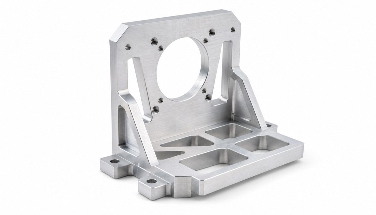
Stiffness, datum layout, material, wall thickness and joint design work together to control repeatability and thermal drift.
Separate Repeatability From Absolute Accuracy
Absolute accuracy describes where the sensor sits relative to the nominal model. Repeatability describes whether it returns to the same position after removal and reinstallation. A mount can be consistently offset yet highly repeatable, or accurate once but unstable after service.
Round pins, diamond pins, shoulder stops or kinematic contacts can constrain the required degrees of freedom without overconstraining the part. Fits such as an H7 locating bore are useful only when the pin tolerance, clearance, wear and assembly method are also defined.
Build The Machining Route Around Stiffness
Critical faces and locating holes should be machined with minimal reclamping. Multi-face structures may benefit from 3+2 or five-axis positioning when it reduces datum transfer and keeps the optical reference tied to the installation base.
Thin walls require low-distortion workholding, balanced stock removal and staged roughing, semi-finishing and finishing. The part should be inspected in a free state unless the drawing explicitly defines a constrained condition.
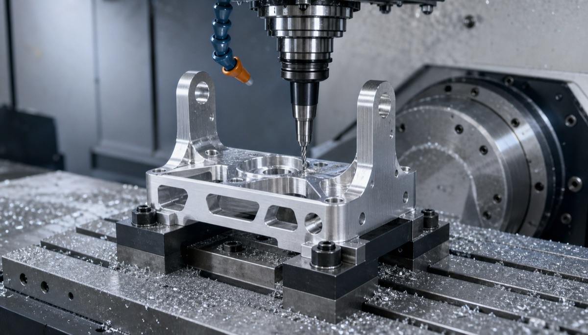
Critical mounting faces, locating holes and optical-axis references should be completed from a controlled datum chain with as few transfers as practical.
Control Thermal Drift With A Budget
Material selection should start from the temperature range, distance between datums and allowable optical movement. Aluminum is light and conductive but expands more than steel, titanium or dedicated low-expansion alloys. Invar may help where drift dominates, but it changes mass, cost and machining strategy.
Thermal isolation, symmetric geometry and matched-material joints can be as important as the base material. A local heat source near one side of a thin bracket may create angular error even if average temperature rise is small.
Inspect Under Defined Temperature And Torque
First-article inspection should cover flatness, perpendicularity, locating-hole size and position, sensor-interface geometry and the full datum relationship. Measurement temperature and stabilization time should be recorded for tight optical tolerances.
Where clamping affects shape, repeat selected measurements after applying the specified fastener sequence and torque. Reinstalling the part several times gives more useful evidence of repeatability than a single CMM result.
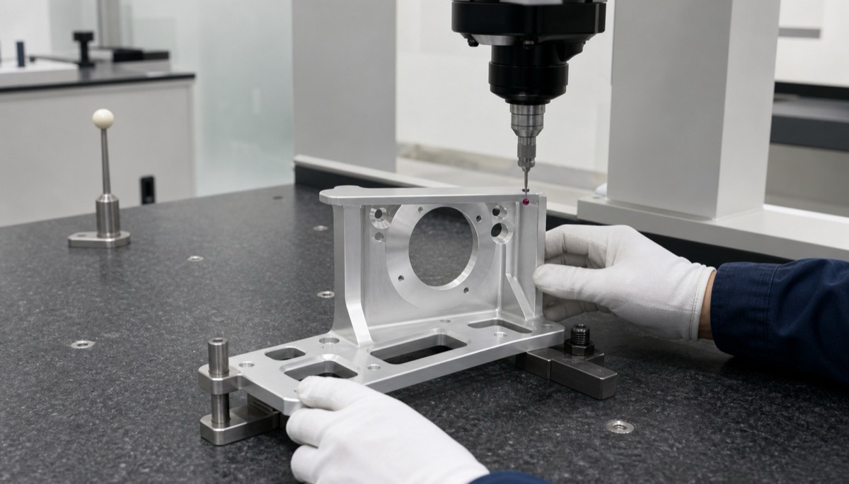
Inspection should reproduce the drawing datum system and, where necessary, verify the part after a defined clamping torque or simulated assembly load.
Information To Send With An RFQ
The supplier needs the functional and environmental conditions that turn a bracket into an optical alignment component.
- Optical axis or detector-plane relationship to mounting faces and holes
- Expected removal cycles, locating method, screw sequence and torque
- Operating temperature range, heat-source location and allowable drift
- Material, finish, low-reflectivity or cleanliness requirements
- Flatness, perpendicularity, position tolerance, measurement datum and reporting scope
Summary
Stable optical sensor mounts require a shared datum system, repeatable locating features, sufficient stiffness and a defined thermal and assembly load budget. Machine the functional features through a controlled route and verify them under the conditions that matter in service.
FAQ
Does ±0.01 mm hole position guarantee optical-axis stability?
No. Face flatness, bracket stiffness, locating method, lever arm, fastener torque and temperature can all move or tilt the optical axis.
When should Invar or steel be considered instead of aluminum?
Consider them when the temperature range and drift budget cannot be met with aluminum geometry or compensation. Mass, corrosion, cost and machining tradeoffs still need review.
Why inspect after applying assembly torque?
Fastener preload can bend a thin mount or change contact at the locating surfaces. A defined torque test reveals the condition the sensor sees in the assembly.
Is a close-fit locating hole enough for repeatable replacement?
No. The pin tolerance, second rotational locator, contact cleanliness, wear and insertion method also determine repeatability.
Ready to get a quote for your CNC machined parts?
Submit your engineering drawings to qiancj@oemach.com. We support prototype sampling and small-batch production with strict tolerance control.