
Define an equipment-side adjustment task
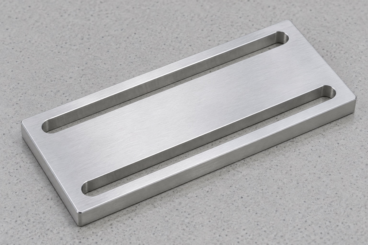
A service module inside a medical laboratory analyzer may need a plate that permits a limited mounting adjustment before separate hardware secures it. The illustrated concept is a flat rectangular aluminum plate with two parallel elongated through slots. Both slots have rounded ends and remain enclosed by metal; there are no extra holes or threads. This is a mechanical adjustment concept, not a calibrated positioning stage or an independent locking device. No actual installation, manufactured specimen or measured result is shown. The equipment team must define the assembly, permitted motion and final holding method before the supplier can establish a manufacturing scope.

Separate slot length from usable travel
Obtain the controlled plate drawing, model, mating support, fastener arrangement and module revision. The nominal length of a slot is not automatically the usable adjustment range of the assembled device. The actual fastener shank, head or washer, nearby hardware and required support area may constrain movement. Review the complete motion envelope without assuming dimensions from an illustration. Clarify the intended initial and final settings, access for adjustment and any separately defined travel stops. A slot that accepts one bolt at one position does not prove that every approved setting remains supported or accessible during service.
Specify the complete closed-slot profile
Define width, end radii, straight portions, depth through the plate and location relative to accepted references. State which surfaces require controlled contact and which provide clearance. A pin fitting at one rounded end cannot verify the entire slot or the relationship between both openings. Avoid extending an end, widening a wall or adding another opening to make an unidentified assembly fit. Such changes need authorization and revised documents. Resolve drawing and model conflicts before finishing. Neither the apparent symmetry of the photograph nor a convenient cutter diameter defines the approved profile, adjustment range or inspection method.
Control mounting faces and thickness
Identify the useful upper and lower faces, finished thickness and required geometric relationships. Distinguish noncontact edge breaks from areas that support the module or purchased hardware. Agree measurement support and the relevant final condition. A plate that appears flat only under strong fixture or mounting pressure should not be accepted on appearance alone. An outside-size reading cannot confirm every functional face. Any required stiffness, preload stability or resistance to movement belongs to the actual assembly specification and separate verification; these properties should not be inferred from the plate's dimensions, material name or polished appearance.
Review both slots as one pattern
The spacing, parallelism and placement of the two openings should relate to the released mounting scheme. Ask whether the slots provide clearance, participate in a locating arrangement or combine with other references elsewhere in the device. Do not assume that two bolts in elongated slots establish a repeatable datum system. The equipment designer must define the intended constraints and adjustment procedure. If the assembly needs additional locating or stop features, keep them explicit and separately controlled rather than adding them informally during machining. Inspect the specified pattern as a related set, not merely as two independently acceptable widths.
Keep the aluminum and final process identifiable
Specify the approved 6061 grade, condition, stock form, lot evidence and purchased final treatment. A silver illustration does not select an anodized, untreated or other finished state. Review operations that may affect slot clearance, thickness or useful contacts and include appropriate final checks. Preserve material identity through blank preparation, slot machining and packing. Material documentation identifies the supplied stock within its scope; it does not establish validated cleaning, biological compatibility, antimicrobial action or medical equipment certification. Do not transfer another bracket's load rating or a standard fastener's properties to this custom adjustment plate.
Plan support before opening the slots
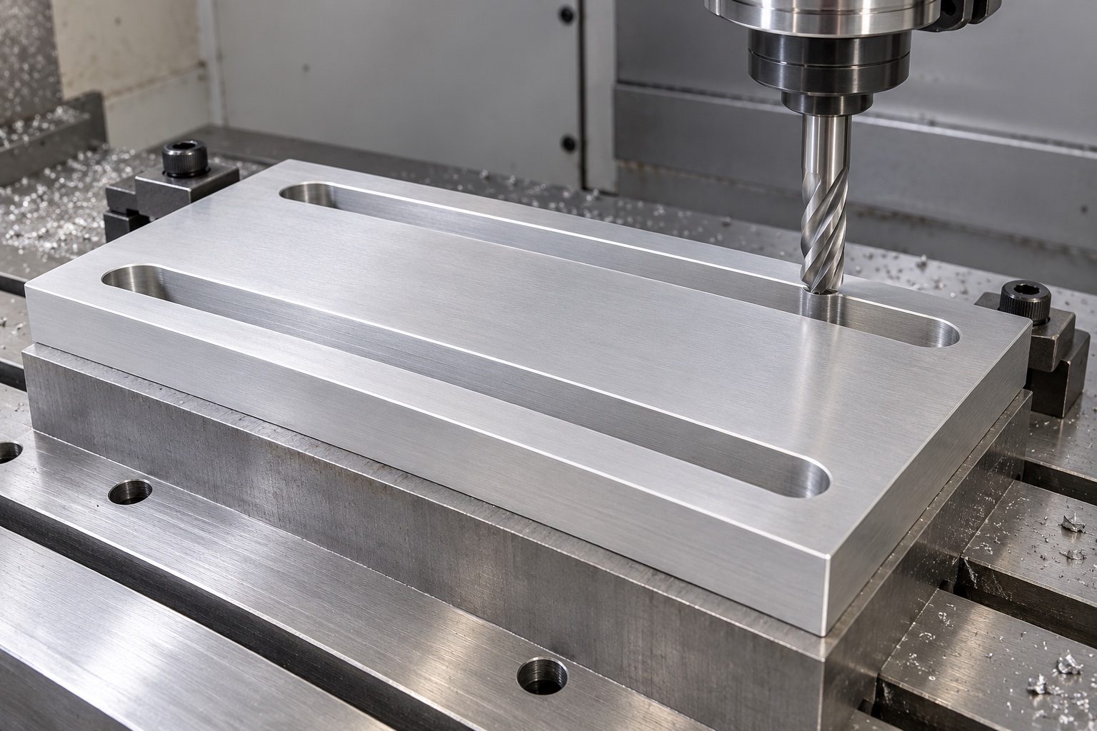
Review holding contacts, tool access and the material remaining between and around the openings. Protect useful faces from clamping marks and embedded chips. Remove chips from references before reorientation. Carr Lane's locating and clamping guidance provides general workholding background, not approval of a fixture for this plate or of the medical equipment assembly. Intermediate measurements can support route development, but final acceptance must address the agreed finished condition. No universal clamping force, machine settings or achieved tolerance is prescribed. A fixture-imposed shape is not a substitute for the released component geometry and inspection plan.
Finish entries without enlarging the adjustment envelope
Inspect slot mouths, rounded ends, outside corners and through-slot exits for attached material or unwanted sharp features. Apply approved edge requirements while preserving useful contact areas and the controlled opening. Hand polishing that changes width or end position requires review rather than being hidden as cosmetic finishing. Cleaning should follow the purchased scope. A smooth surface does not establish low particle generation, validated disinfection or sterile delivery. Define any relevant residue, finish or handling requirement for the actual equipment environment and retain evidence appropriate to that requirement instead of relying on an illustrative machining image.
Match inspection methods to the required features
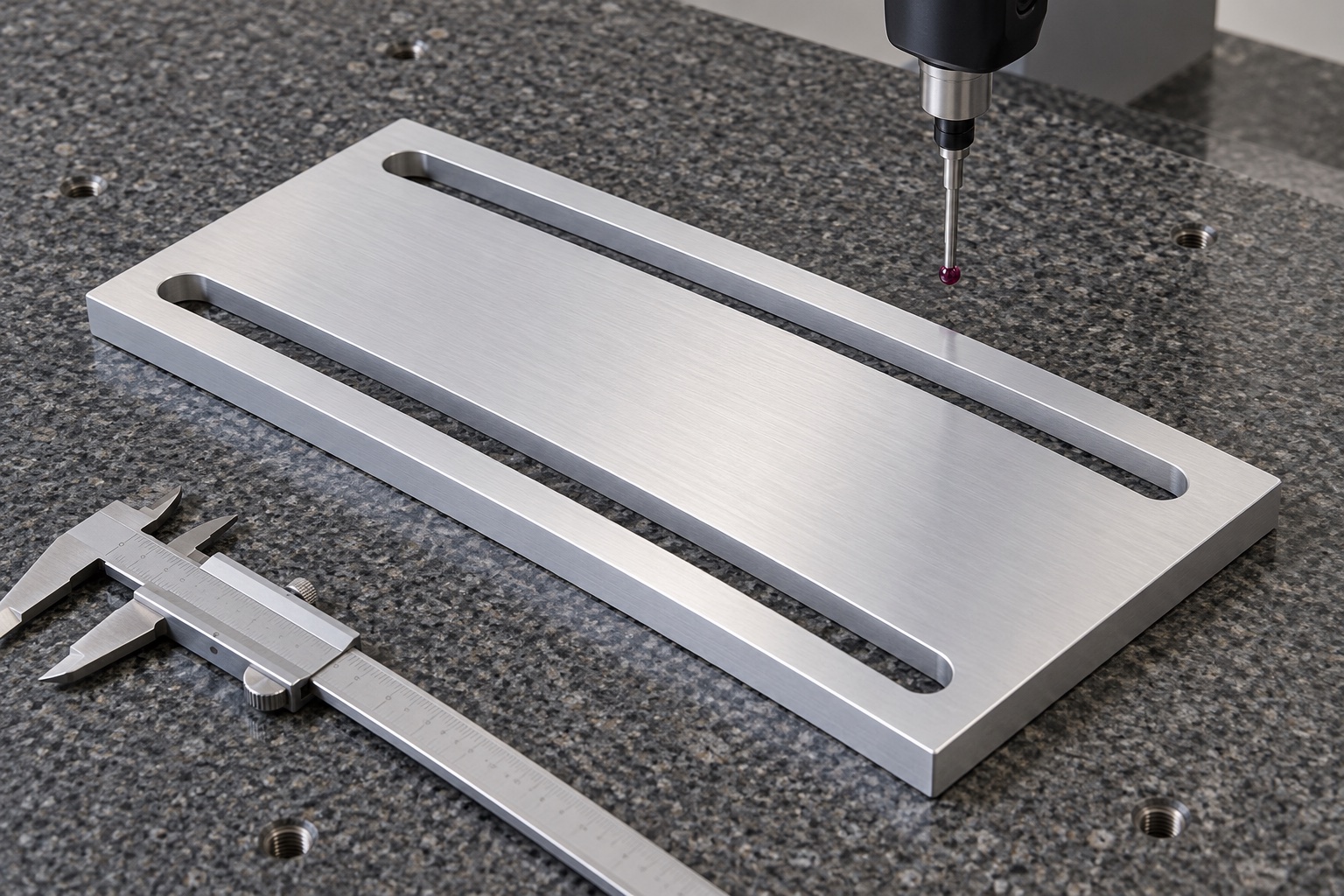
Map slot profile, width, spacing, position, finished thickness, useful faces and specified relationships to accessible methods. Agree references, support and final processing before inspection. A caliper or pin addresses selected characteristics, not every portion of the adjustment pattern. Where probe access is limited, resolve the method before accepting the component. A real report should identify drawing revision, material lot, numbered features and actual observations. A CMM photograph illustrates possible equipment, not an achieved tolerance, verified flatness or complete-device alignment result. Keep component measurements separate from optional observations of the actual mounting assembly.
Bound the optional adjustment trial
An agreed assembly observation may examine access, seating, intended movement and hardware clearance using identified plate, module, support and fastener revisions. Record the installation procedure and the actual retaining arrangement. Easy hand adjustment does not establish preload, vibration resistance, load capacity, positional stability or safe servicing under operating conditions. Those need separately defined evaluation of the complete assembly. Keep trial pieces distinguishable from accepted production. Unexpected interference or rocking should trigger review before altering slot geometry, substituting hardware or using a manually modified plate as an informal universal gauge for other modules and mounting arrangements.
Protect slots and contact faces during transport
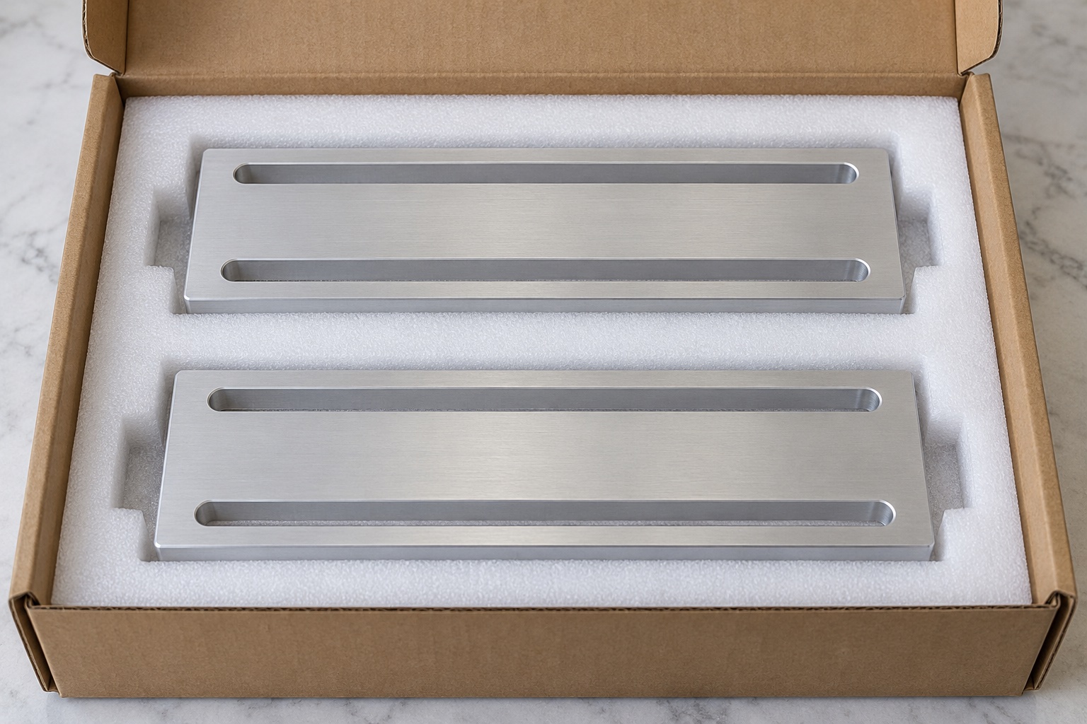
Separate finished plates so loose hardware and adjacent parts cannot strike useful contacts or slot edges. Select supports and pocket sizes that preserve the accepted state without bending the plate. Keep lot, revision, final treatment and inspection status with the shipment. Mechanical protective packaging does not imply sterile supply or validated cleaning. Receiving personnel should distinguish similar outlines with different slot widths, lengths, spacing or thickness before installation. The packaging record should identify the actual supplied component while leaving the equipment team's complete holding, alignment and service qualification as a separate application responsibility.
Prepare an adjustment-specific inquiry
Provide controlled geometry, mating surfaces, hardware, required travel, permissible settings, contacts, material, final processing and inspection deliverables. Identify optional assembly fitting separately from holding and operational qualification. Review changed module geometry, supports, fasteners or treatments before repeating manufacture. Incorporate approved prototype adjustments into revised documents rather than retaining a hand-filed slot as the next production reference. This creates a traceable custom CNC scope without inventing measured positioning performance or treating an accepted two-slot plate as a universally qualified medical equipment adjustment, retention or safety system.
Manufacturer background reference: www.carrlane.com.
FAQ
Does slot length equal usable adjustment travel?
Not automatically. The actual fastener shank, hardware envelope, support area and nearby equipment can limit travel. Define the complete assembly and approved settings. A component drawing and a successful fit at one position do not establish every usable or safe service position.
Do two slots independently lock the module?
No independent locking function is established by the geometry. The real assembly must specify its holding arrangement and relevant evidence. Component dimensions alone do not demonstrate preload stability, vibration resistance, load capacity or positional retention under operating conditions.
Can a pin check the entire opening?
A pin can address selected features within an agreed method, but not every wall, end, position or relation between slots. The inspection plan must cover the actual controlled profile, faces, thickness and pattern in the specified finished condition.
Can the supplier lengthen a slot to fit a sample?
Only through an authorized change reflected in controlled documents and appropriate inspection. Hand filing or milling to suit one unidentified sample should not replace the released geometry or become the hidden production reference for other modules and hardware.
Does 6061 establish medical or cleaning qualification?
No. Grade and material records identify the supplied stock within their actual scope. Finished-component surface requirements, cleaning compatibility and any relevant equipment qualification need separately defined evidence. A silver illustration does not select a treatment or establish sterile delivery.
What should a repeat order review?
Review module and support revisions, hardware, adjustment envelope, slot pattern, useful contacts, thickness, material and final processing. Approved changes belong in revised documents. Keep actual measurement records separate from assumptions copied from another assembly or a visually similar plate.

tanghangyun@oemach.com