
Define the adapter before the drive claim
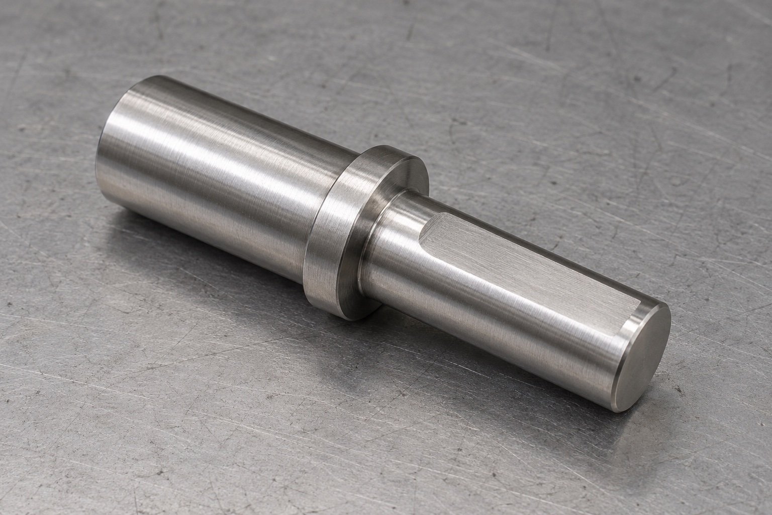
A motor-driven module in medical laboratory equipment may require a separate stepped adapter shaft. This article considers a solid stainless component with a larger round journal, integral shoulder and smaller extension carrying one longitudinal flat. A transverse section through the flat has a D profile. The illustrations show no thread, keyway, cross hole, retaining ring or separate gear. They are concepts rather than approved dimensions or actual production evidence. The presence of a flat does not establish torque capacity, axial retention, fatigue life, backlash, calibration accuracy or the safety of the complete motor-driven equipment mechanism.

Identify both mating drive interfaces
Obtain the controlled shaft drawing, mating hub or coupling, support arrangement, fasteners and actual motor or module revision. The supplier must know which cylindrical surface locates a mating component, which shoulder makes contact and how the flat is intended to be used. Do not assume that a set screw or clamp is present merely because a flat is visible. Motor manufacturer installation instructions are model-specific background, not approval of a custom adapter. Retain the actual mating documents and assembly method rather than transfer a torque or retention value from a different commercial motor installation.
Specify the flat as controlled geometry
Define the flat's depth or remaining section, useful axial length, start and end transitions and position relative to the shaft references. Clarify whether the flat extends to the end or stops before it; the illustration must not replace that requirement. A milled flat is not a keyway, and the supplier should not add another flat to fit an unidentified hub. If angular orientation to another feature matters, specify the relationship and how it will be checked. A convenient wrench dimension or a sample sliding over the shaft does not independently establish the accepted flat geometry.
Relate journals and shoulders to functional references
Specify diameters, useful lengths, shoulder contact areas and required relationships between cylindrical and face features. Identify the surface used to establish the measurement axis and distinguish it from a rough holding diameter. A correct diameter at one location does not verify every specified form or relationship. Where the assembly depends on a shoulder, define useful contact and permitted relief rather than assuming that all visible metal makes contact. The supplier should not introduce a spacer, shorten a shoulder or polish one journal informally to fit an unidentified mating part or a changed support arrangement.
Keep material and final processing explicit
State the approved 316L stock form, condition, material evidence and purchased final processes. Maintain lot identity when turning blanks and transferring them to a milling fixture. Similar silver appearance is not authorization for another stainless grade or a material property claim copied from an unrelated drive component. Define any relevant surface condition and finished-state checks affecting fit. Material identity alone does not demonstrate corrosion performance, wear life, galling resistance, implant suitability or sterile supply. The equipment team must separately define application properties, environmental exposure and the actual mechanical qualification required for its drive installation.
Plan turning and milling references together
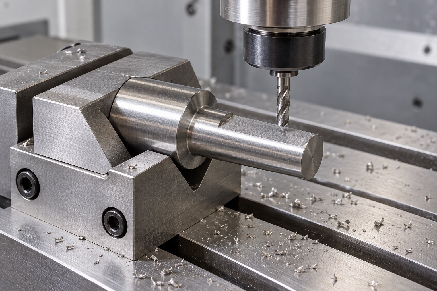
The route should consider how turned diameters, shoulder faces and the later flat remain related after reorientation. Use approved holding contacts that protect useful surfaces and remove chips before relocating the workpiece. Review unsupported length and tool access rather than prescribe one universal fixture or cutting setting. Intermediate checks can help process planning, but final acceptance should address the actual delivered condition. A shaft should not pass solely because a fixture forces a favorable orientation or reading. Record accepted changes to setup or references where they affect the agreed inspection and production scope.
Finish the flat transitions without losing function
Inspect flat boundaries, journal ends, shoulder edges and any approved relief for attached material or unwanted sharp features. Apply the drawing's edge requirements without reducing useful contact length, changing the remaining D section or rounding a controlled shoulder. Hand polishing until an unknown coupling slides on can hide an interface problem and should not replace a design decision. Cleaning and final processing must preserve accepted features. A smooth appearance does not prove low particles, stable torque transfer or sterile delivery. Keep cosmetic observations distinct from measured geometry and separate drive-performance evaluations for the actual assembly.
Map the flat and axis to suitable methods
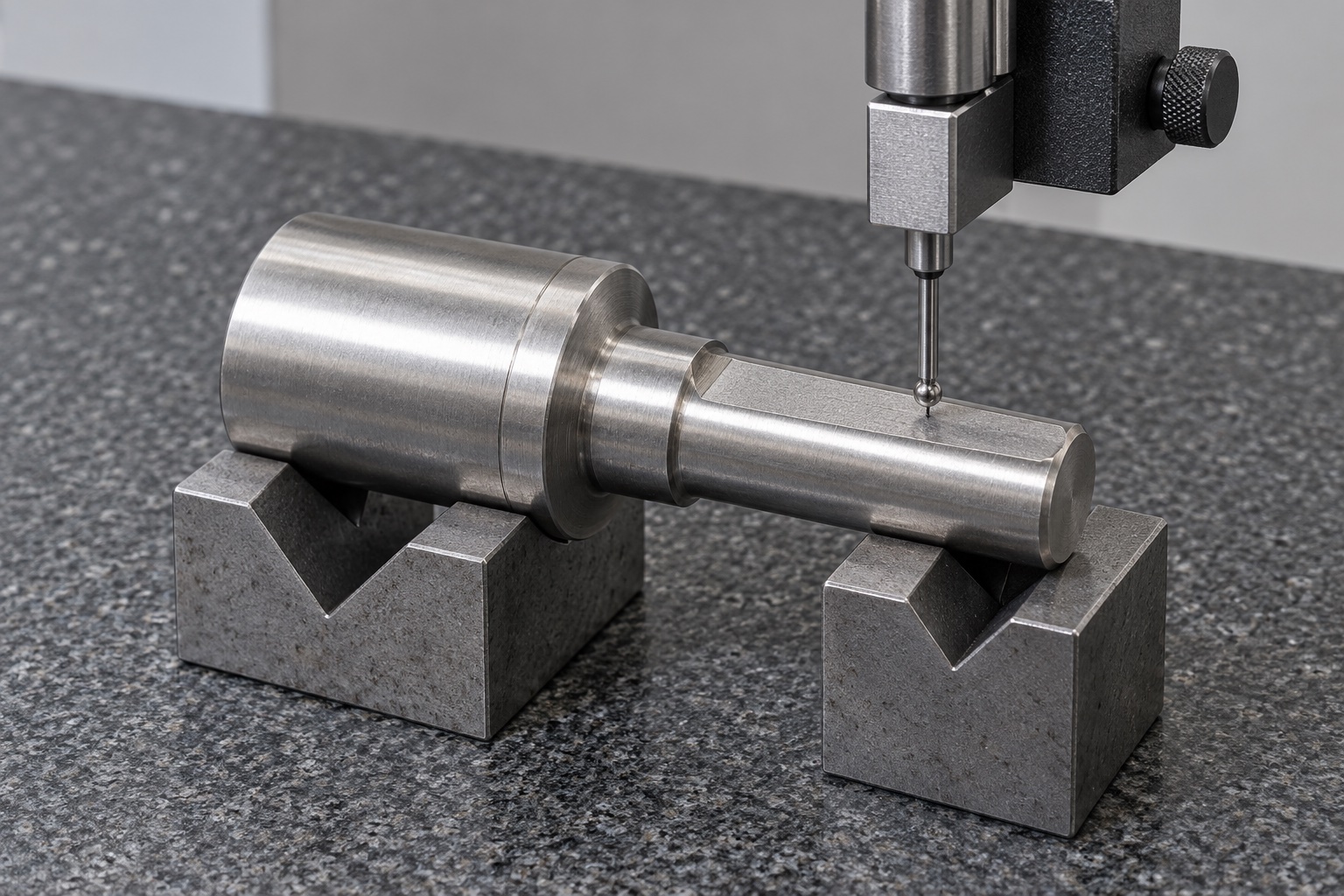
The inspection plan should identify journal size and form requirements, reference establishment, shoulder location and flat geometry, including any controlled orientation. Choose support and contacts that suit the actual shaft and defined final condition. A micrometer reading alone does not verify the flat's axial extent or relationship to the reference axis. A height-gauge or CMM illustration is a possible arrangement, not a complete measurement recipe or an achieved tolerance. Retain numbered characteristics and actual observations on a real report. Clarify inaccessible transitions before acceptance rather than omit them because an outside diameter appears correct.
Treat fitting as a bounded observation
An optional trial can examine entry into the identified hub, shoulder seating, fastener access and expected movement using released component revisions. Record the actual installation method and any approved clamp, screw, lubricant or retaining element. A favorable hand fit does not establish transmitted torque, resistance to loosening, axial pullout, fatigue life or medical equipment safety. Those require separately defined evaluation of the complete drive and its operating conditions. Trial pieces should remain distinguishable from accepted production, and unexpected contact should trigger controlled review before changing either shaft or mating hardware to obtain a convenient demonstration.
Do not turn a material choice into a rating
A stronger-looking shaft or bright stainless surface cannot establish a universal drive rating. The actual smaller section, flat transitions, mating contact, installation method, support and service conditions all belong to the application definition. This article supplies no calculation, numerical load or performance guarantee. A component meeting its dimensional drawing is one part of the evidence, not complete drive qualification. Keep manufacturer instructions tied to their exact commercial products. Do not transfer published settings, load tables or maintenance intervals to a custom adapter without a responsible application review and relevant verification for the actual equipment.
Protect journals and flat edges during shipment
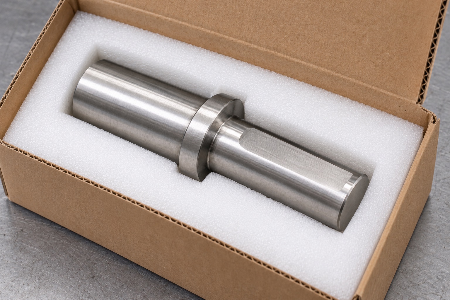
Separate shafts so hard parts cannot strike the useful journals, shoulder contacts or flat boundaries. Support each piece without uncontrolled bending or abrasive contact. Keep loose hardware away from accepted surfaces and preserve material lot, revision, final treatment and inspection identity. Mechanical protective packaging is not sterile delivery. Receiving staff should distinguish similar stepped shafts with changed flat depth, useful length or journal diameter before assembly. Preserve the link between the accepted component and its records before the equipment team performs installation and any independent torque, retention, environmental or maintenance qualification of the medical laboratory mechanism.
Build a mating-specific manufacturing inquiry
Provide controlled models and drawings, both mating interfaces, actual fastening and retention method, useful contacts, flat requirements, journal and shoulder relationships, material, final process and inspection deliverables. Identify optional fit observations separately from drive-performance qualification. Review changed hubs, supports, fasteners, lubrication or service conditions before repeating manufacture. Incorporate approved adjustments into revised documents instead of keeping a manually filed flat as a general production gauge. A clear inquiry establishes a traceable turning and milling project without inventing measured strength or confusing a dimensionally accepted D-profile shaft with a qualified complete medical equipment transmission.
Manufacturer background reference: www.orientalmotor.com.
FAQ
Does one flat establish a torque rating?
No. The flat is controlled component geometry. Torque transfer depends on the actual remaining section, mating contact, fastening, support and operating conditions. No universal rating or measured drive result is provided by this article.
Is a D flat the same as a keyway?
No. A flat and a keyway are different features with different mating interfaces. The supplier should manufacture the released geometry and not add a slot, second flat or other drive feature to fit unidentified hardware without authorization.
Must the flat reach the shaft end?
That depends on the approved drawing. Define useful axial length and both transitions explicitly. An illustrative picture or a hub fitting one sample does not decide whether the actual design requires a flat ending before or at the end face.
Does a micrometer check the complete adapter?
No. It can address selected diameter characteristics. Shoulder position, face relationships, flat geometry and any specified orientation require suitable methods and references in the defined final condition. No single favorable reading establishes the complete part.
Can another motor's installation torque be reused?
Not as an assumed custom-adapter requirement. Manufacturer instructions apply to identified products and assemblies. The actual equipment team must define and qualify its fastening, retention and drive arrangement using the correct mating parts and conditions.
What should a repeat order review?
Review hub and support revisions, flat depth and useful length, journals, shoulders, fastening, retention, material and final processing. Approved changes belong in controlled documents rather than a hand-modified sample or a transferred performance claim from another mechanism.

tanghangyun@oemach.com