
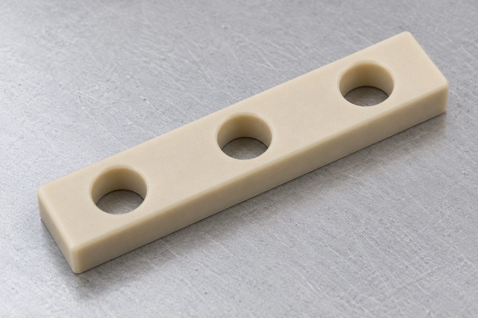
Define a mechanical spacing component
A medical equipment electrical compartment may use a separately machined polymer bar to establish a defined mechanical stand-off beneath a terminal arrangement. This article concerns a natural unfilled PEEK rectangular bar with three plain through holes in one row and flat opposing faces. No terminals, conductors or inserts are included in the illustrative component. The bar is not presented as an approved electrical protective measure. Its dimensions, appearance and material name do not independently establish dielectric performance, creepage, clearance, flammability classification or safety of the complete electrical installation within the medical equipment.

Identify the actual terminal and fastening stack
Obtain the controlled bar drawing and model together with the terminal assembly, support panel, fasteners and installation revision. Identify useful contacts, required stand-off and which holes provide mounting clearance. The supplier should not choose screw length or assume that a metal fastener is electrically isolated. Define any inserts, washers or separate barriers in their own approved documents. Matching a terminal pitch alone does not verify the entire mounting arrangement. Any electrical separation requirement must be defined by the responsible equipment team for the real conductive parts and environmental conditions, not inferred from a polymer photograph.
Specify the exact PEEK grade and evidence
Natural color is not a complete material specification. Identify the approved grade, stock form, condition, lot evidence and any purchased conditioning or final process. Unfilled, reinforced, conductive and other modified PEEK materials are not interchangeable merely because their names share PEEK. Ensinger's machining overview illustrates that different PEEK material variants exist; it does not approve an arbitrary custom bar or transfer medical or electrical qualification to it. Maintain grade identity through blank preparation, machining and shipment. Supplier material documents should be assessed within their actual scope rather than treated as a certificate for the finished electrical assembly.
Define thickness and useful support faces
The stand-off depends on released face geometry and the actual contact arrangement, not only the nominal stock thickness. Specify final thickness, useful land areas and required relationships between faces. Agree how the component is supported during inspection and distinguish a free part from one compressed by installation hardware. Tightening a bowed bar against a panel does not by itself resolve its dimensional acceptance. The equipment team should define the mechanical loading and environmental requirements that apply to the installed assembly. The machining drawing should not acquire unverified electrical or long-term deformation claims through an illustrative acceptance photograph.
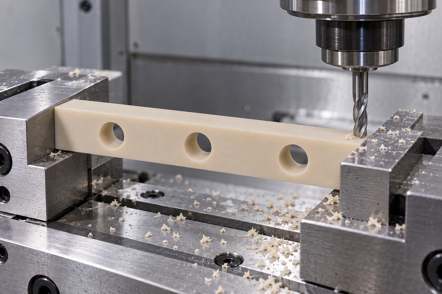
Control the three-hole row relative to contacts
Specify each hole's type, size, spacing and relationship to the useful faces and outer profile. The illustrated holes are plain through features, not threaded insert seats. Check screw and terminal access against identified hardware. A gauge pin entering a bore can support a specified size check, but does not automatically establish the full row position, thickness or final contact geometry. Do not open an end hole into a slot to fit one sample unless that change is authorized. Additional recesses or metal inserts would require a new geometry, material-interface and assembly review rather than an undocumented finishing adjustment.
Plan stock removal and support together
Review the bar length, remaining sections, stock direction where relevant and holding contacts before selecting machining operations. Protect accepted surfaces from concentrated clamping or embedded chips. A polymer bar should not be accepted solely because fixture force holds it in a favorable shape. Sharp suitable tooling, chip removal and heat management belong to the approved process plan; this article does not prescribe universal cutting values. Any conditioning or intermediate treatment should be grade- and geometry-specific and agreed with the material supplier where appropriate. Final dimensioning and inspection must refer to the condition actually specified for the delivered component.
Keep bore exits and surfaces controlled
Inspect both ends of every through hole, outer edges and face transitions for attached material or unwanted sharp features. Apply released edge requirements without reducing useful support or changing the accepted hole row. Do not use polishing to conceal a shifted bore or a seating discrepancy. Cleaning should address the purchased scope and preserve material identity. A clean-looking ivory surface does not prove electrical insulation performance, measured particles, validated cleaning or sterile delivery. If the actual application requires limits on residues or contamination, specify suitable methods and acceptance evidence instead of relying on a general packaging description.
Inspect without excessive measurement force
Map thickness, faces, hole sizes, row position and required relationships to appropriate methods, support and environmental conditions. Identify contacts that could deform the component and agree how they will be used. A caliper photograph is not a complete inspection plan or an achieved tolerance. Gauge observations should be recorded for their specified characteristics rather than expanded into claims about the full terminal assembly. Retain drawing revision, material grade, final condition and actual inspection results. Where the part changes after release from a fixture, investigate the component and process rather than simply increasing restraint during the final check.
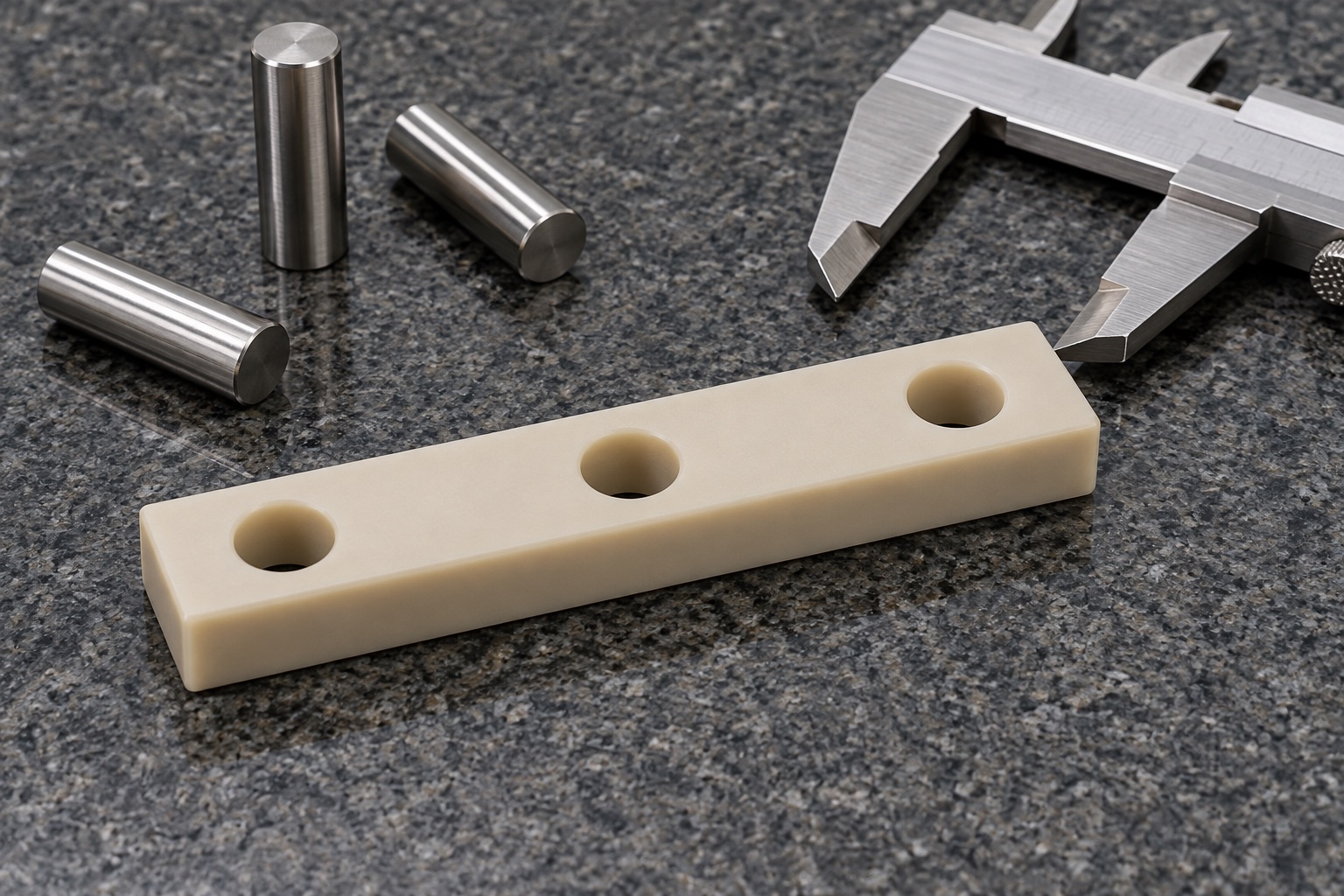
Separate assembly fit from electrical qualification
An optional trial may observe stand-off, seating, screw access and terminal alignment using identified component revisions and an approved installation method. Record any washers, barriers, inserts or other parts in the actual stack. Mechanical fit does not establish dielectric strength, insulation coordination, flammability, heating behavior or medical electrical safety. Those require separately defined application evaluations and evidence for the complete installation. The manufacturing supplier should not select an electrical test level from the polymer name. Keep dimensional acceptance, optional fit observations and system-level qualification distinct in quotations, records and any proposed production release.
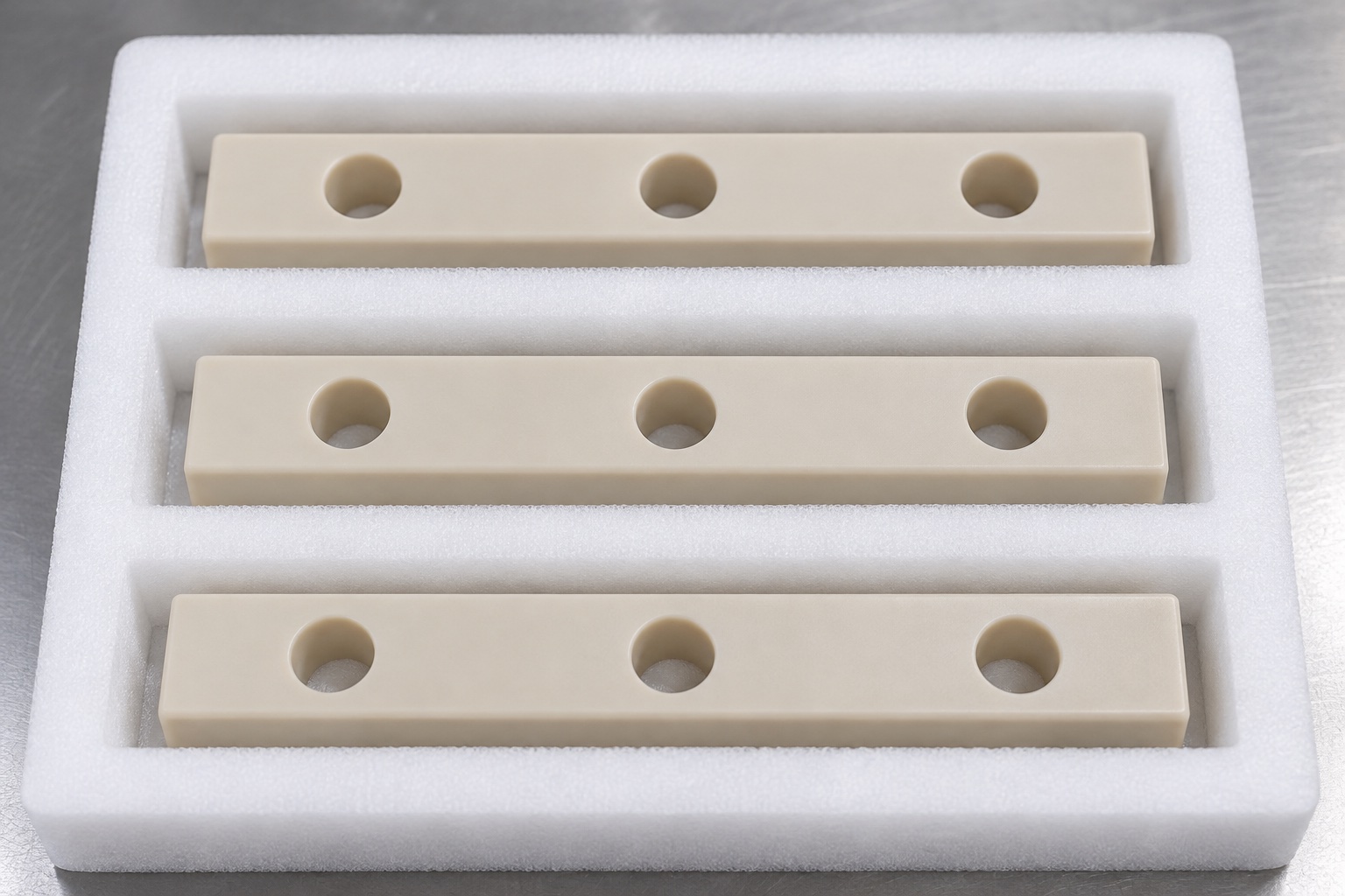
Protect the bar without introducing assembly claims
Separate finished bars in suitably sized pockets or sleeves so metal hardware cannot strike holes or embed in accepted faces. Restraint should not bow the long section. Keep packaging material and cleanliness requirements within the approved supply scope; mechanical protection is not a sterile barrier or proof of insulation performance. Preserve grade, lot, revision and inspection identity during shipment. Similar three-hole bars can differ in thickness, spacing or material modification, so receiving identification matters. The equipment team should confirm the actual variant before installing conductors and performing its independent electrical and environmental qualification.
Review changes beyond the outside outline
A repeat order needs review when the terminal pitch, fasteners, panel, contact areas, material grade, coating elsewhere in the stack or intended environment changes. Do not retain the same bar drawing merely because its outline still fits. Approved prototype adjustments must become controlled revisions. Electrical requirements may impose different design constraints, but a supplier should not invent them from a previous installation. Preserve the relationship between released geometry and the actual assembly definition. This prevents a mechanically convenient polymer strip from being treated as a universally qualified electrical isolation component across unrelated medical equipment configurations.
Prepare a bounded manufacturing inquiry
Provide the model and drawing, approved PEEK grade, terminal and panel interfaces, actual hardware, useful support faces, hole-row requirements, final condition, inspection deliverables and packing scope. Identify any application-specific qualification as a separate agreed responsibility. Clarify missing dimensions before machining rather than copy a manually drilled sample. Ask for traceable first-part records on a real order, without assuming a generic tolerance or guaranteed electrical property. A well-defined inquiry establishes a practical custom CNC project while keeping material evidence, component dimensions and the complete medical equipment electrical installation's acceptance requirements appropriately distinct.
Manufacturer background reference: www.ensingerplastics.com.
FAQ
Is any natural-colored PEEK grade acceptable?
No. Specify the exact approved grade, stock form and evidence. Reinforced, conductive and other modified materials can differ. Appearance and the general PEEK name do not authorize substitution or establish finished assembly qualification.
Does this bar provide proven electrical isolation?
No electrical performance result is established. It is a mechanical spacer concept. The responsible equipment team must define and evaluate the actual conductive parts, fasteners, geometry, material and operating environment for any required protective function.
Are the three holes threaded insert locations?
No. The illustrated holes are plain through holes. Threads, inserts, slots or recesses require an authorized design and assembly review. The supplier should not add metal hardware or change the hole row to fit an unidentified terminal sample.
Why specify measurement support and force?
The agreed method must address the actual polymer component without relying on a distorted condition. Thickness, faces and hole relationships need appropriate support and contacts. A favorable restrained reading is not automatically evidence of the delivered free component's conformity.
Does protective packing mean sterile supply?
No. Mechanical transit protection preserves accepted surfaces and identity within the purchased scope. Sterility, validated cleaning, residue limits and electrical qualification require separately specified processes and evidence, not assumptions based on a clean foam tray.
What should change-control review cover?
Review terminal and panel revisions, fasteners, contacts, hole spacing, thickness, exact grade, final condition and service environment. Incorporate approved adjustments into controlled documents rather than use a manually altered bar as a universal electrical or dimensional reference.

tanghangyun@oemach.com