
Define a threaded retaining component
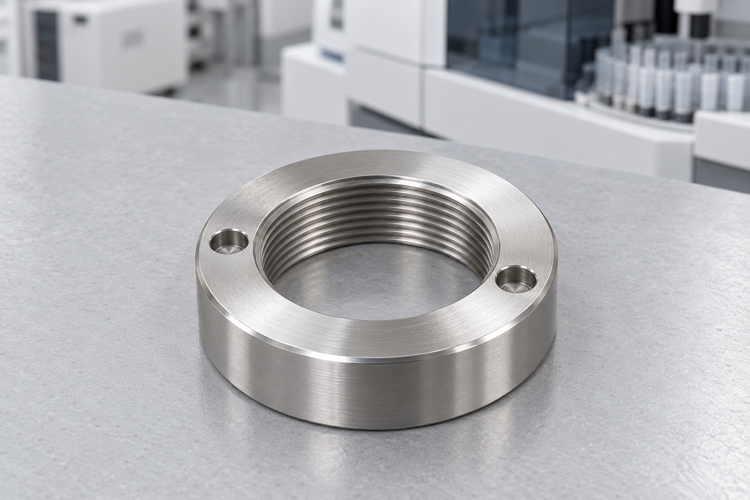
A medical equipment module may use a round internally threaded nut as part of an approved axial retaining arrangement. Two face holes can provide a tool interface, but the nut's shape does not establish self-locking behavior or a qualified clamp force. This article concerns equipment-side CNC manufacture, not a universal joint design. Illustrations show a proposed 316L annular nut with smooth cylindrical exterior, internal through-thread and two opposed blind axial face holes. They are concepts, not an actual delivery, measured production record or validated medical equipment retention system.

Identify the sleeve and complete contact stack
Obtain the controlled nut drawing, actual mating external thread, retained module, shoulder or seating arrangement, installation method and equipment revision. Clarify which annular face contacts the approved stack and whether spacers or another retention element are part of the assembly. A nut that turns onto one sleeve does not establish the intended final seat or required engagement. The responsible designer must release those relationships. The supplier should not shorten a nut, remove a spacer or substitute a sleeve merely to obtain a favorable hand-fit demonstration with incomplete or unidentified components.
Make thread definition and useful length explicit
Specify thread system, size, pitch, direction, required class or acceptance criteria, useful engagement and permitted entry or runout regions. Resolve conflicting model and drawing information before machining. The visible threaded depth in a concept image is not a usable engagement specification. Review tool access and remaining annular material as part of process planning. A thread gauge addresses its defined characteristics; it does not independently establish sufficient engagement, clamp force or resistance to loosening in the actual module stack. Those requirements need their own approved design and assembly evaluation.
Relate the seating face to the thread
Define the useful annular contact area and its required relationship to the thread and other functional references. Thickness and outer diameter alone may not establish the face relationship that controls seating. Clarify where entry breaks, reliefs or processing are allowed to reduce the useful face. An exterior surface convenient for holding is not automatically the correct inspection reference. Resolve ambiguity before turning rather than select whichever setup gives favorable results. Preserve the approved contact definition so subsequent finishing or a trial fit does not silently change how the nut bears against the actual retained module.
Specify the two face holes as tool features
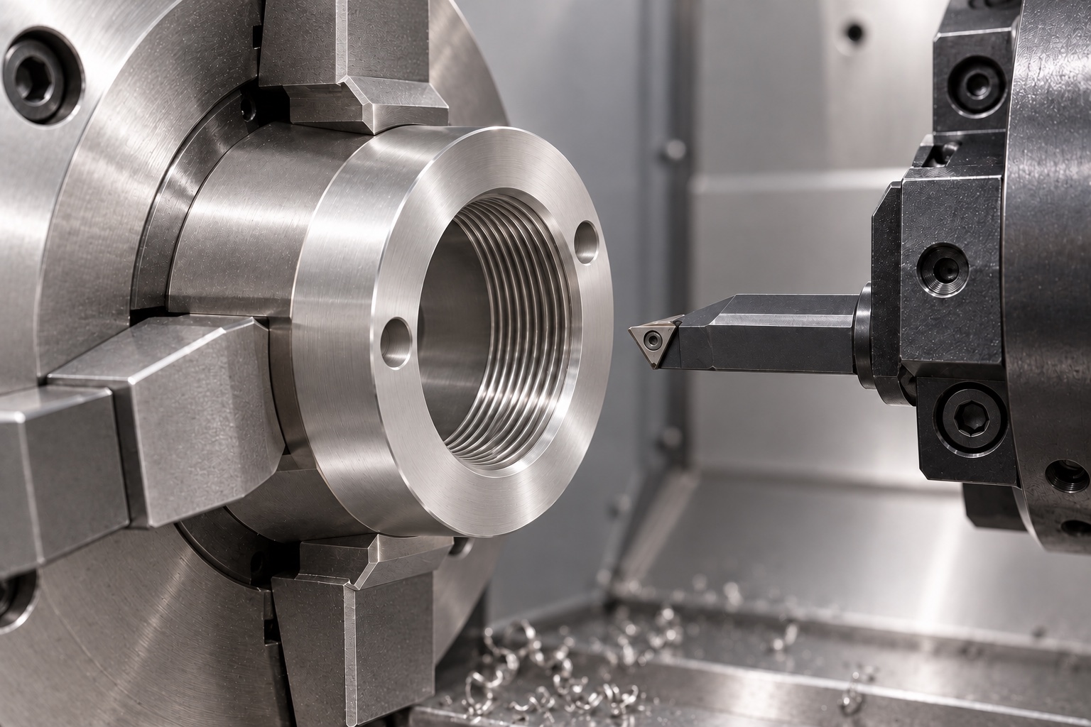
Define hole size, spacing, depth, axis direction and relevant relationship to the thread and seating surfaces. Blind face holes are not interchangeable with radial holes, slots or through holes. GEDORE's face-spanner listing identifies pin diameter and height as tool characteristics; this illustrates why engagement geometry matters, not that a particular tool approves this custom nut. Review the actual released tool and access envelope. The supplier should not drill deeper, widen a hole or substitute another drive form merely to fit an unidentified spanner or make an assembly demonstration easier.
Keep installation torque outside the picture
The equipment designer must define the actual assembly method, any specified torque, permitted lubricants and any separate anti-loosening arrangement. Do not infer torque from nut diameter, material, a tool photograph or successful hand rotation. Tool access at the final installed location should be reviewed without treating easy engagement as evidence of adequate clamping. A component report cannot establish module retention under vibration, repeated service or operating loads. Keep installation observations, dimensional acceptance and any clamp-force, loosening or complete-equipment qualification separate and linked to their actual configuration and procedure.
Specify stainless stock and final process
Identify the approved 316L stock, condition, material evidence and purchased surface processing. A stainless designation does not make the nut equivalent to another catalog fastener or establish medical certification. Preserve lot identity through turning, face-hole machining, finishing and shipment. Cleaning, passivation or another treatment must follow the agreed scope with relevant finished-state checks, not be inferred from a bright surface. Material identity and appearance do not demonstrate measured corrosion resistance, sealing, quantified cleanliness or sterile supply. Those properties need separate application-specific requirements and evidence when relevant to the medical equipment program.
Plan holding for the annular section
Review roughing, thread and face finishing, face-hole machining and setup transfer so accepted relationships remain controlled after unclamping. Holding force should not make a distorted ring appear conforming or damage the thread. Protect useful seating and tool-contact regions during reorientation and remove chips from locating surfaces. No universal cutting parameters or machine sequence are prescribed here. Intermediate checks may inform process planning, but final acceptance should address the agreed finished condition. A nut turning smoothly only while restrained is not evidence that its released thread and seating geometry meet the drawing.
Finish entries without changing contact
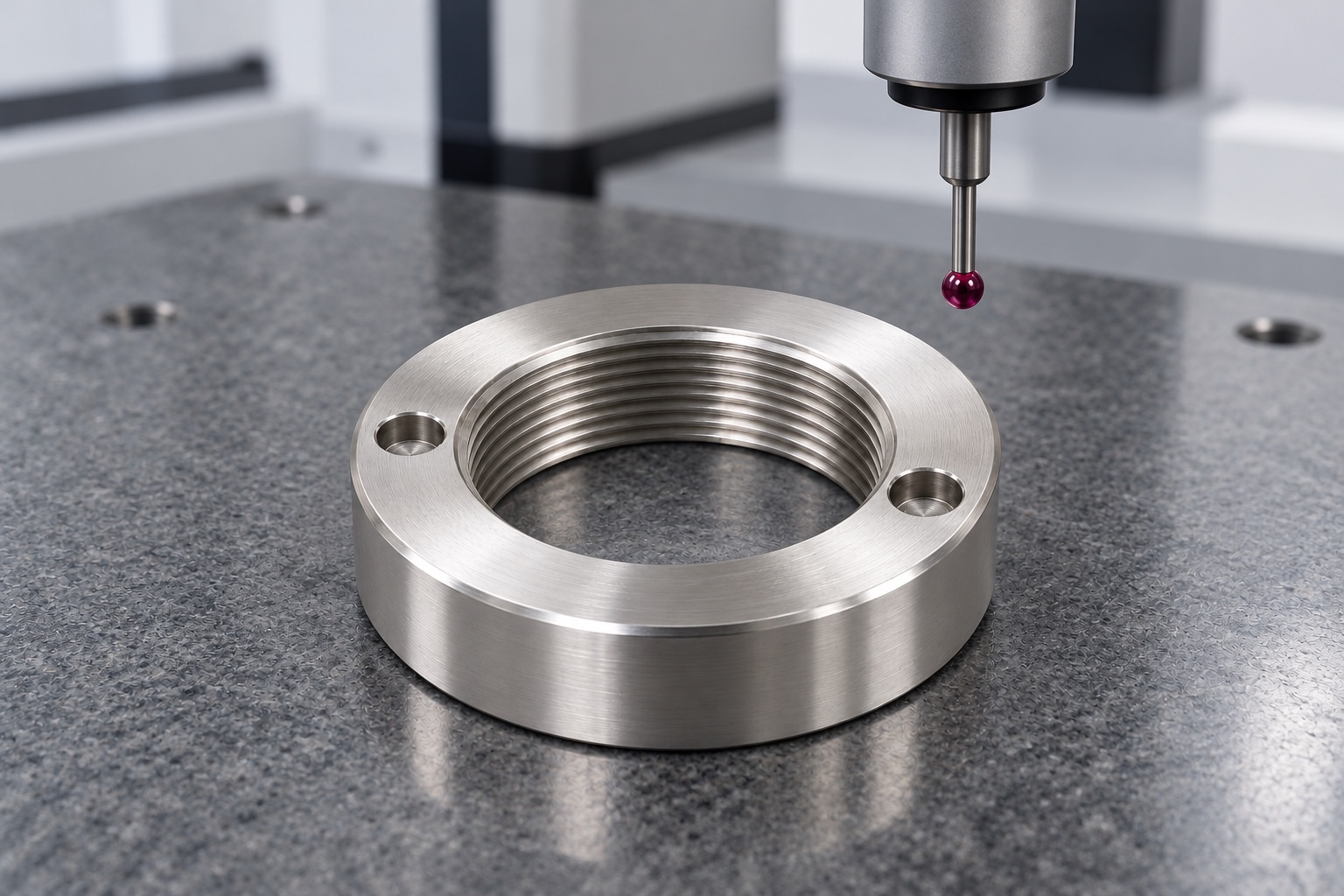
Inspect thread entries, exits, blind tool holes, face edges and exterior corners for attached material or unwanted sharp features. Apply approved edge requirements without reducing useful thread engagement, tool contact or annular seating area. Polishing until an unidentified sleeve feels free can conceal a geometry issue and should not substitute for a design decision. Cleaning and final processes must preserve accepted features. A bright finish does not establish galling resistance, validated cleaning, a fluid seal or low particles. Keep authorized surface changes traceable rather than rely on a manually adjusted nut as the next production reference.
Inspect dimensions and assembly observations separately
Map thread requirements, useful face, thickness, tool holes and reference relationships to accessible methods in the defined final state. Identify support, treatment and actual inspection criteria before manufacture. An optional trial can examine entry, seating, engagement and tool access with identified nut, sleeve, module and spanner revisions. Record the installation procedure and any approved lubricant or retention component. A favorable fit does not establish clamp force, vibration resistance, fatigue, sealing or medical equipment safety. Unexpected contact should trigger controlled review before altering the nut or substituting another stack component to complete the demonstration.
Protect threads and seating faces in transit
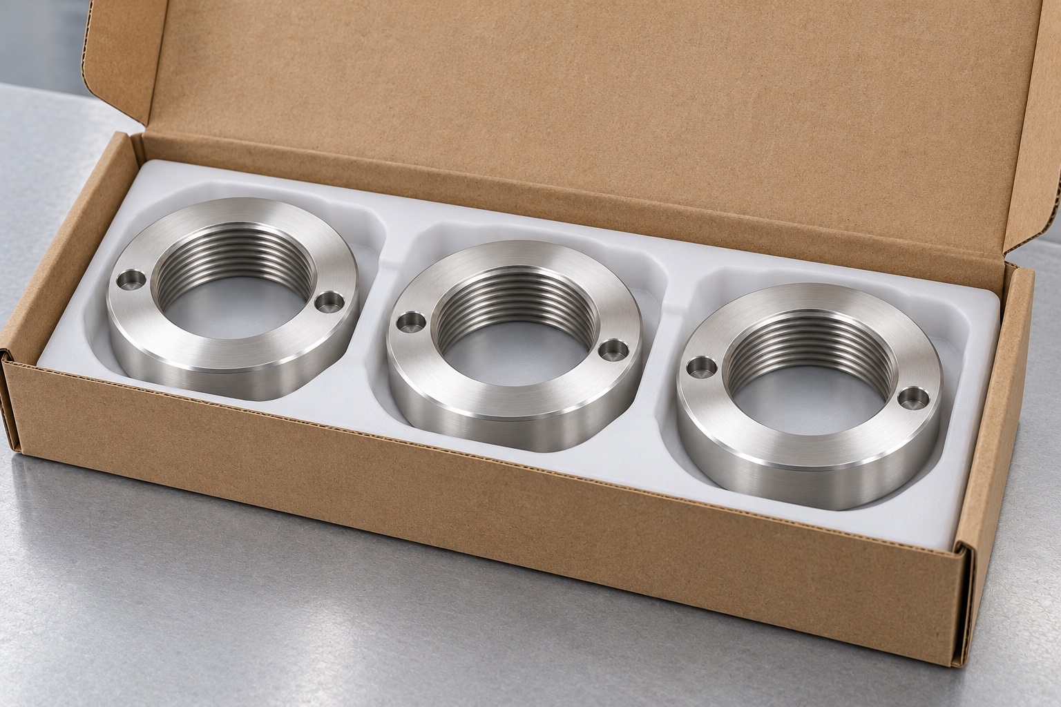
Separate nuts so hard parts cannot strike internal thread entries, annular contacts or blind-hole rims. Support the ring without bending it through packaging pressure and protect accepted surfaces within the purchased cleaning scope. Mechanical packaging does not mean sterile supply. Preserve material lot, revision, final treatment and inspection status with the shipment. Receiving staff should distinguish thread direction, pitch, thickness and tool-hole variants, prototypes and released production. Maintain the identity of the accepted nut before the equipment team performs installation and any independent retention, maintenance or cleaning evaluations for the actual medical module assembly.
Build a stack-specific manufacturing inquiry
Provide the controlled model and drawing, actual sleeve thread, module and seating stack, useful contact and engagement requirements, tool identity, installation access, material, final processing and inspection deliverables. Identify optional assembly observations separately from torque, clamp-force and anti-loosening qualification. Review changed sleeves, spacers, tools, lubricants or service conditions before repeating manufacture. Incorporate approved prototype adjustments into revised documents. This defines a traceable custom CNC scope without inventing measured strength, treating two tool holes as a locking mechanism or confusing a conforming stainless nut with a qualified medical equipment retention system.
Manufacturer background reference: www.gedore.com.
FAQ
Is this nut a self-locking fastener?
No self-locking behavior is established by the proposed concept. The two face holes provide a tool interface, not an anti-loosening mechanism. Any locking or retention requirement must be defined and evaluated for the actual nut, sleeve, stack and operating conditions.
Does a thread gauge prove the assembly retains a module?
No. It checks specified thread characteristics. Useful engagement, seating, stack geometry and installation method need their own requirements. Clamp force, loosening resistance and complete module retention cannot be inferred from a passing thread gauge or successful hand rotation.
Can blind face holes be replaced by radial holes?
Not without an authorized design decision. They have different axes, access and tool-contact geometry. The approved drawing and assembly must identify the required drive interface. An unidentified spanner should not trigger an undocumented hole or depth change.
Does this article prescribe an installation torque?
No. Torque and any lubricant, locking feature or installation procedure belong to the actual approved assembly. A tool photo, nut diameter or material identity cannot establish an appropriate universal torque, clamp force or resistance to loosening.
Does the bright stainless surface imply a fluid seal?
No. The proposed equipment-side nut is not a qualified sealing component. Appearance also does not establish galling resistance, measured corrosion performance, validated cleaning or sterile supply. Any relevant application property needs separately defined and verified evidence.
What should repeat-order review include?
Review sleeve thread, retained module, seating stack, engagement, tool, access, material, final process, lubricant and service conditions. Preserve controlled revisions instead of copying a manually adjusted ring or transferring retention assumptions from another medical equipment installation.

tanghangyun@oemach.com