
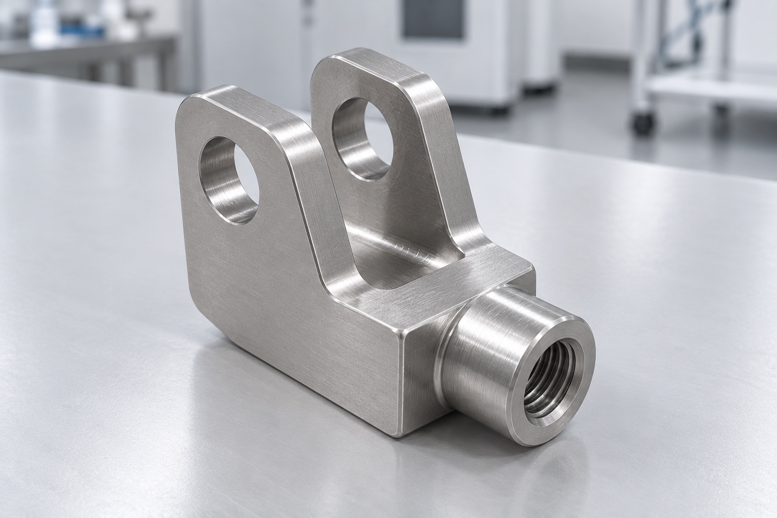
Treat the clevis as part of a complete linkage
A medical equipment mechanism may connect a rod to a lever through a fork-shaped clevis and a separately retained pin. The clevis provides specified contact geometry, but a machined fork alone is not a qualified linkage. This article addresses equipment-side CNC manufacture, not a universal safety-critical design. Illustrations show a proposed stainless steel U-shaped head with two arms, aligned transverse holes and a threaded boss at the solid heel. They are concepts without an installed pin, measured load result, actual production sample or validated medical equipment performance claim.

Identify all mating components first
Obtain the released clevis drawing, mating lever or joint piece, pin, retention components, rod and assembly revision. Ganter's GN 751 catalog describes fork heads with pins as linkage elements; it is background only. Its listed stainless steel version uses AISI 304, so it does not certify or rate this different proposed 316L concept. Do not transfer catalog dimensions, load behavior or conformity to a custom fork by visual similarity. The responsible equipment designer must define the actual material, interfaces, retention and operating requirements for the complete medical mechanism.
Define useful fork clearance and contact
Fork gap should be related to the approved mating component, useful side contact, installation route and permitted movement. Specify the relevant internal faces and transitions rather than only the largest opening at the tips. Root radii and arm thickness can affect the available envelope. A lever entering the gap does not establish acceptable side clearance throughout travel. Resolve model and drawing conflicts before milling. Do not widen the fork merely to make an unidentified mating piece fit, because that changes the controlled interface without establishing the behavior of the actual linkage.
Control the paired pin bores together
Specify bore size, useful bearing regions and the required relationship between the two arm holes and other functional references. Two individually acceptable diameters do not automatically demonstrate the required common pin path. Review access and inspection before choosing the machining sequence. A loose pin passing through can support a defined fit observation, but should not replace every geometric requirement. The responsible designer must define the appropriate relationship and tolerance, rather than asking the supplier to infer a universal coaxiality requirement or accept a convenient drilling result as evidence of complete joint conformity.
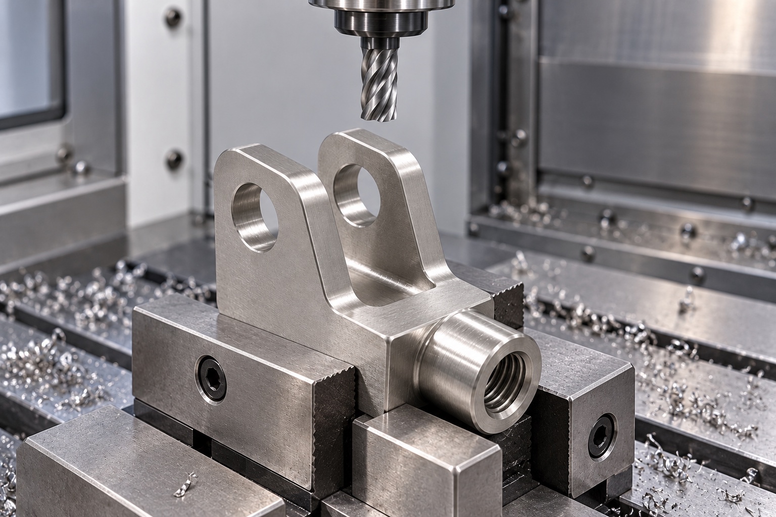
Relate rod attachment to the fork
When the actual design uses a threaded boss, specify thread designation, useful engagement, entry, depth and relationship to the pin axis and fork references. Thread depth and usable engagement are not identical to the drilled depth. Clarify any permitted root transition and tool clearance before machining. Do not add a thread, change its hand or deepen it merely to accommodate an unidentified rod. The full attachment and locking arrangement belongs to the approved assembly. A thread gauge result does not independently establish linkage capacity, loosening resistance or adequate engagement under operating loads.
Preserve the released root geometry
The solid heel and internal arm transitions should follow the controlled model and drawing. Tool access may require an agreed radius, but the supplier should not silently substitute a larger relief or remove material to simplify machining. A smooth transition is not evidence of a qualified stress distribution or fatigue life. The equipment designer must evaluate loads and operating conditions for the actual geometry. Manufacturing review should identify conflicts early, keeping authorized changes traceable and avoiding hand-finished roots whose final shape is no longer represented in the released inspection and design documents.
Specify stainless steel and final processing
Define the approved 316L stock, condition, material evidence and any required final surface process. A stainless designation does not make the part equivalent to another supplier's fork or establish medical certification. Preserve lot identity through turning, milling, finishing and shipment. Cleaning, passivation or another process must follow the purchased scope with relevant finished-state checks; they are not prescribed solely by a silver illustration. Material identity and surface appearance do not establish measured corrosion resistance, quantified particles, sterile delivery or compatibility with every medical equipment maintenance and cleaning exposure.
Plan support during fork machining
Review the sequence for the heel, boss, slot and paired holes so functional relationships remain controlled after release. Holding should support the component without squeezing the arms together or forcing them into an apparently correct gap. Clear chips from locating contacts before changing setups. No universal cutting parameters or single tool path are prescribed here. Intermediate checks can inform the route, but final acceptance should address the agreed finished condition. A pin inserted while the arms are restrained is not automatically evidence that the released clevis meets the drawing's gap and bore relationships.
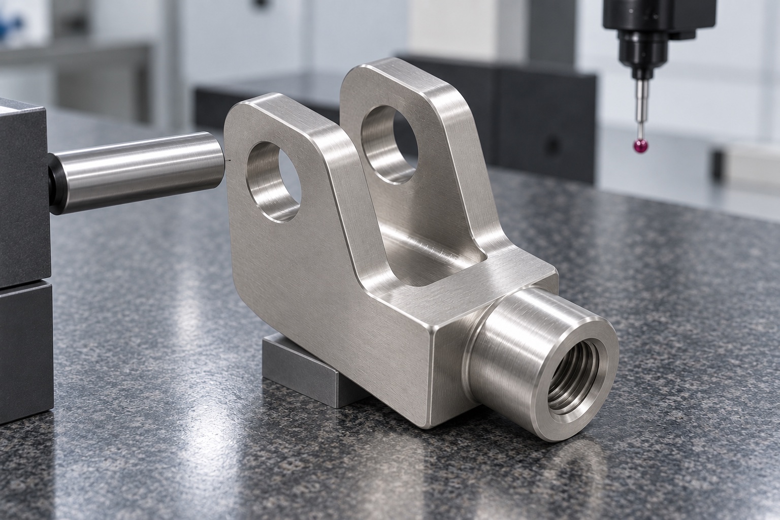
Finish bore exits and internal edges carefully
Inspect pin-bore entries and exits, slot boundaries, arm tips and thread entries for attached material or unwanted sharp features. Apply the approved edge requirements without consuming useful bearing length or broadly rounding the internal contact faces. Polishing until a pin moves easily can change the interface and should not replace a design decision. Cleaning and final treatment must preserve accepted geometry. A bright fork does not demonstrate low wear, safe pin retention, qualified release force or a validated clean assembly. Those properties require their own explicit evaluation when relevant to the medical equipment program.
Separate dimensional checks and linkage trials
Map fork gap, arm geometry, paired bores, attachment thread and reference relationships to accessible methods in the defined final state. An optional trial can examine pin insertion, articulation clearance and specified access with identified components. Record pin retention and rod configuration as part of the trial scope. Neither a favorable fit nor a component report establishes static capacity, fatigue life, wear, vibration resistance or medical equipment safety. Trial parts must remain identifiable. Unexpected contact should trigger controlled review before modifying a bore, widening the gap or substituting a different pin to complete the demonstration.
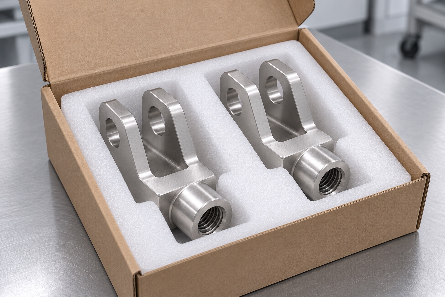
Protect arms and interfaces during shipping
Separate clevises so neighboring hardware cannot strike the arm tips, bore edges or threaded boss. Packaging should support the solid body without bending the arms or pressing debris into the fork gap. Protect threaded entries within the agreed scope and preserve material lot, revision, final treatment and acceptance status. Mechanical packaging is not sterile supply. Receiving staff should distinguish handed configurations, different threads, altered prototypes and accepted production. These controls preserve the identity of the inspected component before the equipment team performs installation and independent linkage performance or maintenance evaluations.
Build an assembly-specific inquiry package
Provide the released model and drawing, exact mating piece, pin and retention details, rod configuration, movement envelope, gap and bore relationships, material, final process and inspection deliverables. Identify optional assembly observations separately from load and fatigue qualification. Review changes to pins, mating thickness, threads, root geometry or operating conditions before repeating manufacture. Incorporate authorized prototype adjustments into controlled documents. This defines a traceable custom CNC scope without copying another manufacturer's product rating, inventing measured strength or treating dimensional conformity as proof of a qualified medical equipment linkage.
Manufacturer background reference: www.ganternorm.com.
FAQ
Does a pin passing through prove the paired bores conform?
Not automatically. It can support a limited fit observation with an identified pin. The drawing may also control individual sizes, useful bearing lengths and relationships to the fork and attachment references. Those requirements need agreed methods rather than a passing-pin demonstration alone.
Can catalog fork-head ratings be applied to this concept?
No. The proposed 316L geometry is not a rated catalog product. Different materials, dimensions, pins, retention and operating conditions require their own evaluation. A manufacturer's background page does not approve the custom component or transfer its product conformity and performance claims.
Why distinguish drilled depth from thread engagement?
The usable thread region depends on the specified thread and transitions, not just the bottom of a drilled hole. The approved drawing and assembly must define required engagement. A thread gauge or rod fitting by hand does not establish linkage capacity or loosening resistance.
Can the arms be squeezed during acceptance?
Acceptance must use the agreed measurement and support condition. Restraining the arms can conceal a released gap or bore relationship that differs from the observed state. Document the method instead of treating a forced fit as proof of final component conformity.
Does the article claim fatigue or static load results?
No. It provides manufacturing and inspection considerations, not measured strength or a safety rating. The complete linkage, actual material, pin, retention and operating conditions need separate design evaluation and qualification when those requirements apply.
What changes need review before repeat manufacture?
Review mating thickness, pin and retention, thread and rod, arm and root geometry, material, final processing and operating conditions. Preserve authorized revisions rather than copying a hand-adjusted fork or transferring performance assumptions from another medical mechanism.

tanghangyun@oemach.com