
Define an equipment-side mounting component
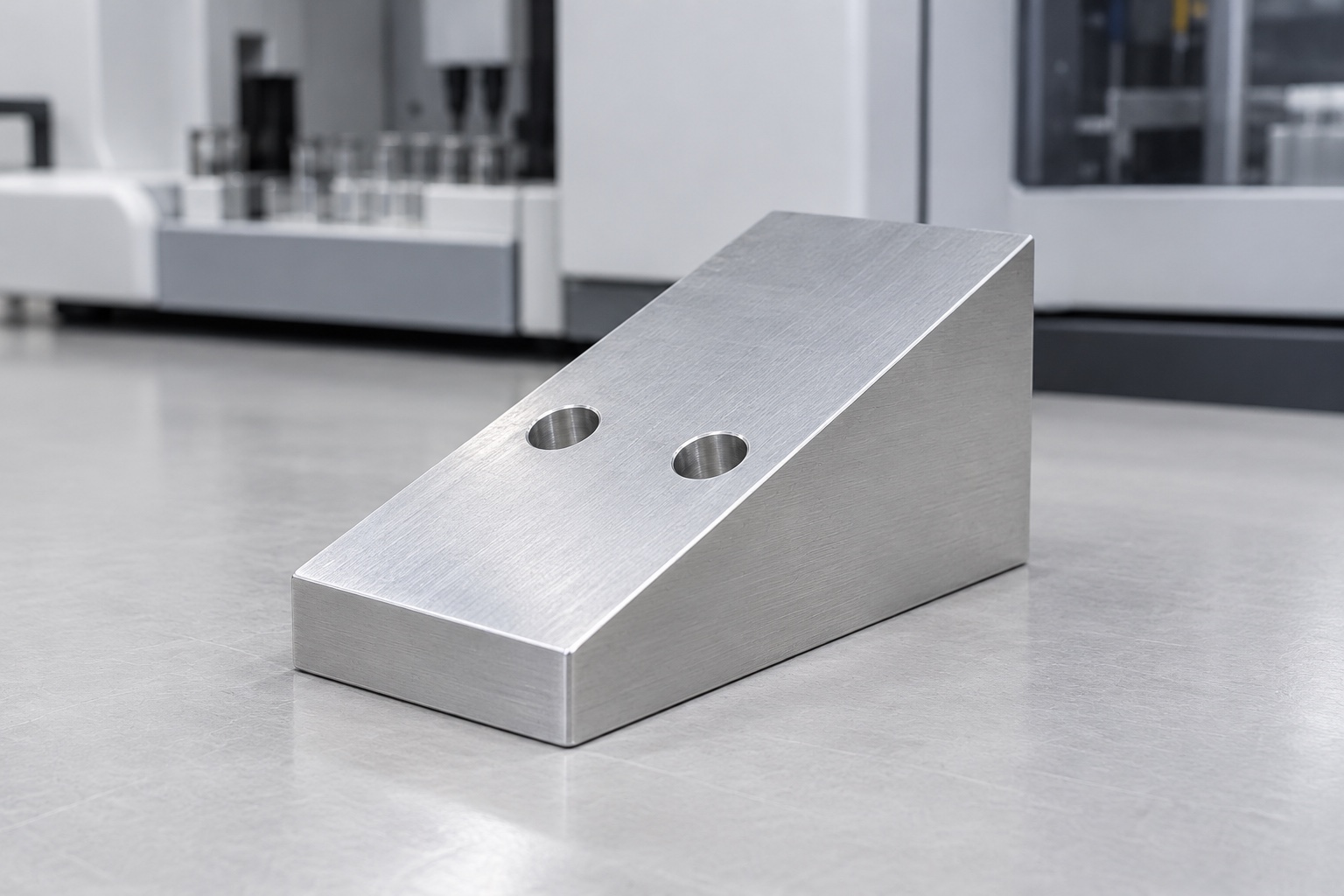
A medical analyzer can require a fixed inclined mounting surface for a sensor or its approved carrier. A machined wedge provides geometry between that surface and a supporting base, but does not establish the sensor's calibrated direction or analytical performance. This article addresses CNC manufacture of an equipment-side mounting component. Illustrations show a proposed solid aluminum wedge with a flat underside, thick low end, higher opposite end and two plain holes across the inclined face. They are concepts, not a drawing, measured production record or validated medical instrument installation.

Start with the actual sensor and installation
Identify the exact sensor, carrier, support surface and controlled installation revision. Clarify whether the inclined face supports the sensor directly or another mounting component. Cable direction, connector access and enclosure clearance can change the usable region. Thorlabs describes fixed-angle optomechanical mounts as background examples of inclined mounting surfaces; those catalog products do not approve this proposed medical analyzer wedge or establish its material, angle or compatibility. The responsible equipment designer must release the actual geometry and operating arrangement before manufacturing decisions are based on a familiar-looking mounting concept.
Separate angle from height and location
An inclination value alone does not define a sensor mounting wedge. The drawing should relate the useful upper face to the base, relevant side reference, mounting pattern and required height. Clarify whether the angle applies to a local contact region or the complete face. An acceptable angle can coexist with an incorrect height or displaced hole pattern. Resolve model and drawing conflicts before machining. The supplier should not move the pattern or shorten the wedge merely to match an unidentified sample, because that can change the installed sensor position despite preserving the nominal slope.
Make hole direction unambiguous
Specify each hole's axis, position, size and relationship to the inclined surface and base. A hole normal to the slope is not interchangeable with one normal to the underside. State the intended fastener head contact and any required counterbore separately; the illustrative concept has plain holes only. Review tool access and possible exit interference before committing to a setup. Do not infer a thread or hidden fixing from a photograph. The complete attachment arrangement, including any separate base retention, belongs to approved assembly documents rather than an assumption made by the machinist.
Review the full mounting and access envelope
Check sensor insertion, fastener access, cable routing and service removal against neighboring components in the released installation. A sensor resting on the wedge does not prove that it can be tightened or removed inside an enclosure. Identify prohibited contacts and any approved adjustment features. Temporary shims or adhesive should not become undocumented production instructions. Unexpected interference needs a controlled decision before altering the inclined face, hole direction or cable space. Keep these assembly observations separate from acceptance of the machined component and any later sensor alignment or instrument calibration procedure.
Specify aluminum and finished condition
An inquiry should identify the approved aluminum grade, condition, stock form and required material evidence. A proposed 6061 wedge is not a general recommendation for every sensor or cleaning environment. Define any final surface treatment, masking and dimensional checks after processing. The bare silver illustrations do not prescribe an untreated delivery. Preserve material lot identity through manufacturing and shipment. Neither a material certificate nor a surface appearance demonstrates corrosion resistance in the actual installation, grounding continuity, validated cleaning, sterile delivery or suitability for every medical analyzer exposure and maintenance procedure.
Plan the inclined-face machining references
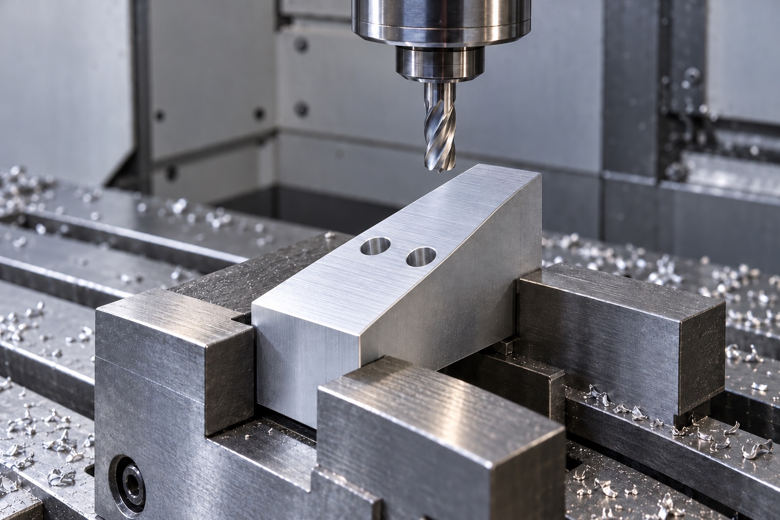
Review stock preparation, base establishment, roughing, finishing and setup transfer so the inclined face remains related to its functional base after release. Holding on convenient raw sides can obscure which surfaces actually define the installation. The fixture must support the component without introducing misleading restraint during acceptance. Clear chips from locating contacts before a setup change. No universal cutting values or machine architecture are prescribed here. Intermediate checks can support process development, but the final report should address the agreed finished component state and the drawing's relationships rather than machine coordinates alone.
Preserve usable face area during finishing
Edge breaks should remove unwanted sharp features without consuming the designated sensor or carrier contact region. Inspect hole entries, exits and the narrow end of the wedge for attached material. Broad polishing can alter useful flat areas or hole contact geometry and must not substitute for a released requirement. Cleaning and any later treatment should follow the order and preserve accepted features. A smooth-looking part does not prove thermal contact conductance, electrical continuity, particle performance or a qualified clean surface. Those properties require their own defined scope and application-specific evidence when relevant.
Measure related features in the final state
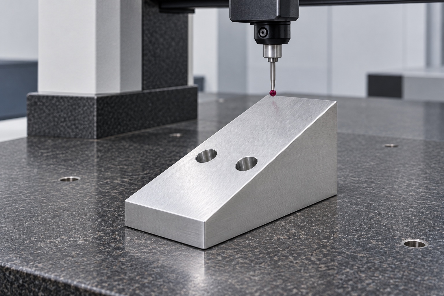
Translate the drawing's angle, height, face, base and hole requirements into accessible inspection methods before production. Identify the supported measurement condition, final treatment and relevant contact region. An inclinometer reading alone may not verify face form, hole position or height relative to the actual base. Agree how inaccessible or ambiguous requirements will be resolved rather than replacing them with convenient dimensions. An identified assembly sample can support a limited observation, but should not silently become a universal gauge. Keep actual results linked to revision, material lot and the component's purchased inspection scope.
Keep mounting trials distinct from calibration
An optional trial can examine seating, fastener access, cable clearance and removal with identified sensor, carrier, wedge and support revisions. Record the installation method and any approved adjustment components. A successful hand assembly does not establish calibrated sensor direction, detection sensitivity, optical alignment, thermal stability or analytical accuracy. The complete equipment team must define and evaluate those requirements independently. Trial wedges should remain distinguishable from accepted production. A manually altered prototype should enter a controlled change process before it is treated as a manufacturing reference for another sensor or instrument configuration.
Protect reference surfaces during transport
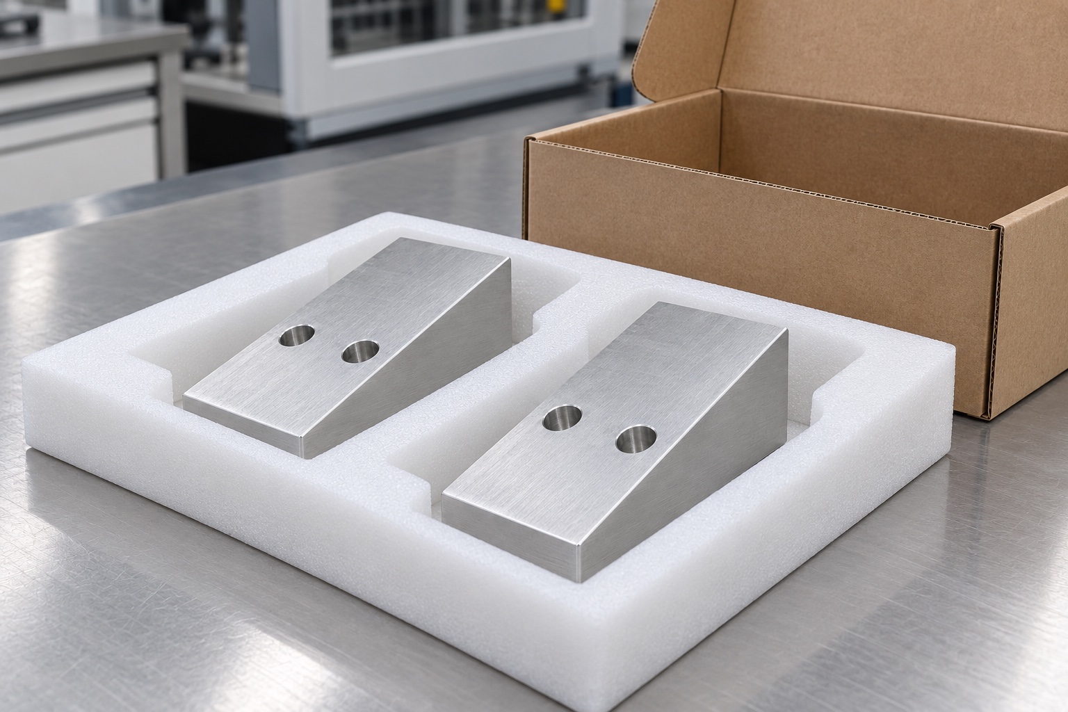
Pack wedges individually so loose fasteners and neighboring edges cannot strike the base or inclined mounting face. Select supports that do not press on a narrow contact region or hide debris under the part. Protective packaging is not sterile delivery. Preserve grade, lot, revision, treatment and acceptance status with the shipment. Receiving staff should distinguish opposite inclinations, different hole directions and prototype adjustments, even when all variants look like simple silver wedges. Maintain the relationship between the accepted component and its installation documents before any later assembly, cleaning or alignment procedure begins.
Build a configuration-specific inquiry
Provide the controlled model and drawing, exact sensor and carrier details, angle and height relationships, hole axes, complete attachment arrangement, access envelopes, material, final treatment and inspection deliverables. Identify optional assembly observations separately from calibration and equipment qualification. Review changes to sensors, cables, support geometry or processing before repeating manufacture. Incorporate authorized prototype adjustments into revised documents. This gives the CNC supplier a traceable mechanical scope without asking the supplier to invent the sensor angle, claim an achieved tolerance without measurements or treat dimensional acceptance as proof of a validated medical analyzer installation.
Manufacturer background reference: www.thorlabs.us.
FAQ
Does an accepted wedge angle prove sensor alignment?
No. The wedge's dimensional acceptance concerns specified component geometry. Actual sensor alignment, calibration and analytical performance depend on the complete installation and require separate approved procedures. Angle, height, mounting position and the sensor's own references should not be treated as interchangeable evidence.
Are holes normal to the slope and base equivalent?
No. They describe different axis directions and can require different attachment and machining arrangements. The controlled drawing must identify the intended direction, position and fastener contact. A photograph of two holes cannot resolve an ambiguous hole-axis requirement.
Does the silver illustration specify bare aluminum?
No. It shows a proposed concept, not a delivery specification. Grade, condition, finish, masking and final inspection must follow the approved order. Appearance does not establish cleaning compatibility, grounding continuity or measured corrosion resistance in a medical analyzer.
Can shims be introduced during an assembly trial?
Only through an authorized decision when they affect the controlled mounting arrangement. Record their identity and installation. Unrecorded shims or adhesive must not replace the released geometry or become an informal production baseline for other sensors, carriers or support structures.
Is one angle reading sufficient for inspection?
Not necessarily. The drawing can also control face form, height, base relationships and hole position. Each specified characteristic needs an agreed method and final-state condition. A favorable assembly observation cannot automatically replace drawing-based component acceptance.
What information should a repeat order preserve?
Preserve sensor and carrier identity, base and angle references, hole direction, attachment configuration, access space, material and final process. Review any change explicitly rather than copying a modified sample or transferring calibration claims from another equipment configuration.

tanghangyun@oemach.com