
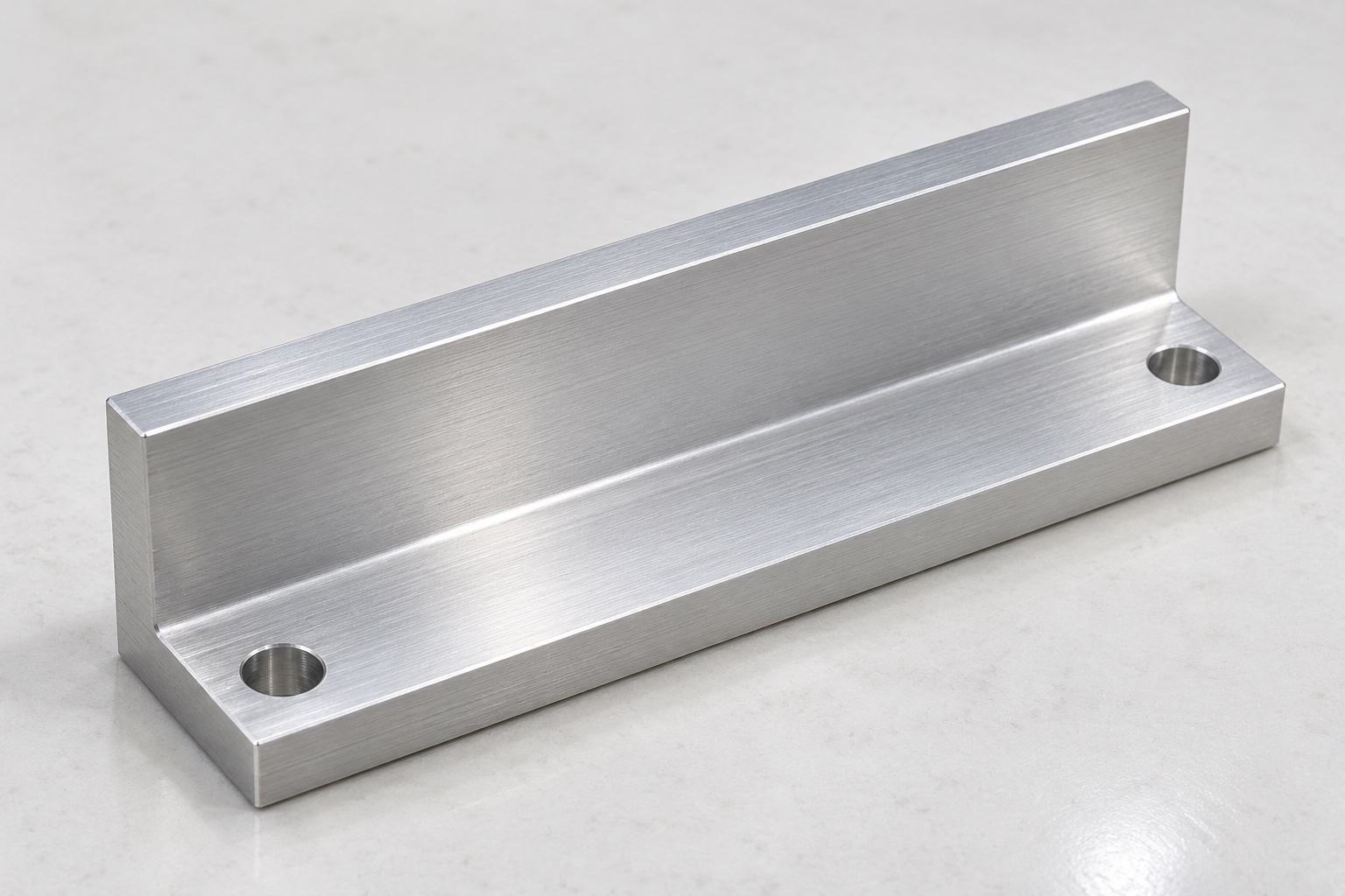
Define the jaw as one component of a mechanism
A medical analyzer may hold a microplate with a mechanical clamp whose contact jaws are separately machined components. The jaw connects the mounting arrangement to a defined external region of the plate. Its contact ledge and upright face need a controlled definition, but machining them does not validate a complete handling process or analytical result. This article addresses equipment-side CNC manufacture, not a universal clamping design. Illustrations show a proposed stepped aluminum jaw without an actuator, real microplate or measured production record. Actual geometry must follow the responsible equipment designer's approved configuration.

Identify the exact plate and contact boundary
Obtain the approved microplate variant, relevant external dimensions, lid configuration and device installation documents. Plate format alone does not define every skirt, flange or contact feature. Thermo Fisher's guide illustrates the variety of microplate formats and well designs; it is background rather than approval of this jaw. Clarify whether the jaw contacts the external side, skirt or another released feature. Do not infer contact with wells, sealing film or a lid from an illustrative ledge. Each plate and accessory combination needs its own controlled interface review before manufacture.
Separate contact intent from clamping force
The designer should define the surfaces intended to support, locate and restrain the plate, including which contacts are not permitted. A CNC supplier can manufacture those features but should not invent actuator force, clamp travel or a universal safe load. A jaw fitting around an empty plate does not establish that the plate remains undamaged during operation. Review the complete mechanism and actual plate condition separately. Any proposed contact pad, insert or change in contact width requires authorization rather than being added informally to make a prototype feel more secure.
Relate the ledge and upright face to mounting
Specify the relationship between the horizontal contact ledge, upright contact face, base and mounting holes. The functional reference system should follow the approved assembly rather than the easiest raw edge to measure. Clarify whether an internal corner radius is permitted and which portion of the ledge is useful contact. A broad edge break can reduce that area. Resolve conflicting model and drawing requirements before machining so the supplier does not silently choose a convenient interpretation that changes the plate's support height, side location or clearance to neighboring components in the actual analyzer.
Review entry and release access
Include the plate's approach, removal direction and neighboring component envelopes when reviewing the jaw. A satisfactory final seated position does not prove that the plate can enter or leave without interference. Consider any approved lid, gripper or other handling component as part of the actual configuration. The machining supplier should not trim the jaw, omit a lid or substitute a plate to obtain an easy demonstration. Record where contact occurs and obtain a controlled decision before changing the geometry, handling sequence or acceptance scope used for the equipment-side component.
Specify the aluminum and final treatment
The inquiry should identify the approved aluminum grade, condition, stock form and material evidence. A proposed 6061 jaw is not automatically suitable for every plate material or cleaning environment. Specify any final treatment, masking and relevant finished-condition inspection. Bare silver illustrations do not prescribe an untreated delivery. Preserve material lot identity through machining and shipment. Appearance and material documentation do not establish measured friction, particle generation, cleaning compatibility or sterile supply. Those requirements belong to the actual application and must be evaluated independently when included in the equipment program.
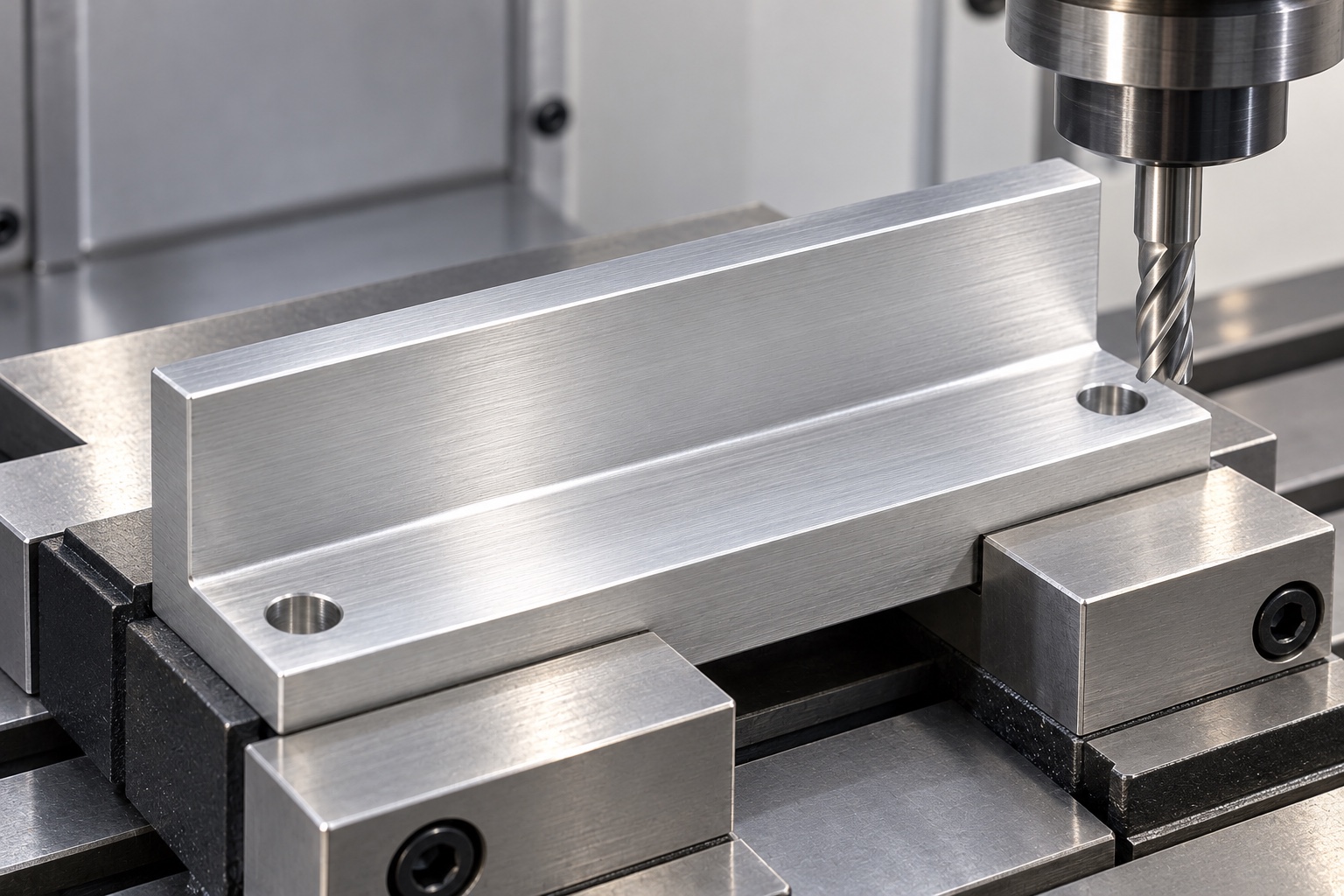
Support the stepped section during milling
Plan stock removal and holding so the upright wall and lower ledge remain related after the jaw is released. Review fixture contact regions, roughing, finishing and any setup transfer before selecting the route. Keep chips away from locating faces and avoid using excessive force to make the jaw appear straight against a fixture. No universal cutting values are prescribed here. Intermediate checks can help assess the route, but final acceptance must address the agreed component condition rather than only dimensions observed while the stepped section is restrained in the machine.
Finish contact edges without changing function
Inspect hole exits, ledge boundaries and upright-wall ends for attached material or unwanted sharp features. Apply the released edge requirements without broadly rounding the working contacts. Polishing until a plate slides easily can change a controlled feature and should not replace a design decision. Cleaning follows the purchased scope and must preserve the contact definition. If a final process alters dimensions or surfaces, agree the relevant checks. A smooth-looking jaw does not prove low particle generation, non-damaging plate contact, validated decontamination or the cleanliness status of an entire medical analyzer.
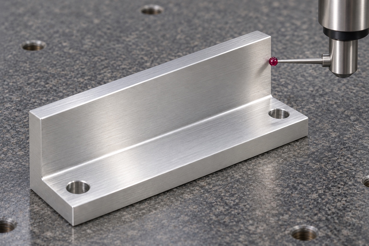
Inspect useful contacts and mounting relationships
Map the specified ledge, upright face, base and mounting-hole characteristics to accessible methods using the approved references. Identify final treatment and support during measurement. An outside rectangle and two hole diameters alone may not verify a jaw whose function depends on contact height and relative position. Resolve inaccessible requirements before production rather than reporting convenient substitutes. A plate sample can support an agreed assembly observation but is not automatically a gauge for all acceptance conditions. Keep the component report and any trial observations clearly separated and linked to their actual revisions.
Define the scope of a handling demonstration
An optional trial may examine seating, entry, release and agreed clearances with identified plate, lid, jaw and mechanism revisions. Record the procedure and any authorized contact inserts. A successful demonstration does not establish clamping capacity, repeated positioning, plate damage resistance, spill prevention or analytical performance. Those need separate evaluations for the complete installation and actual operating conditions. Trial jaws must remain distinguishable from accepted production. Do not turn a hand-adjusted sample or one successful empty-plate movement into an undocumented baseline for other plate variants or medical analyzer configurations.
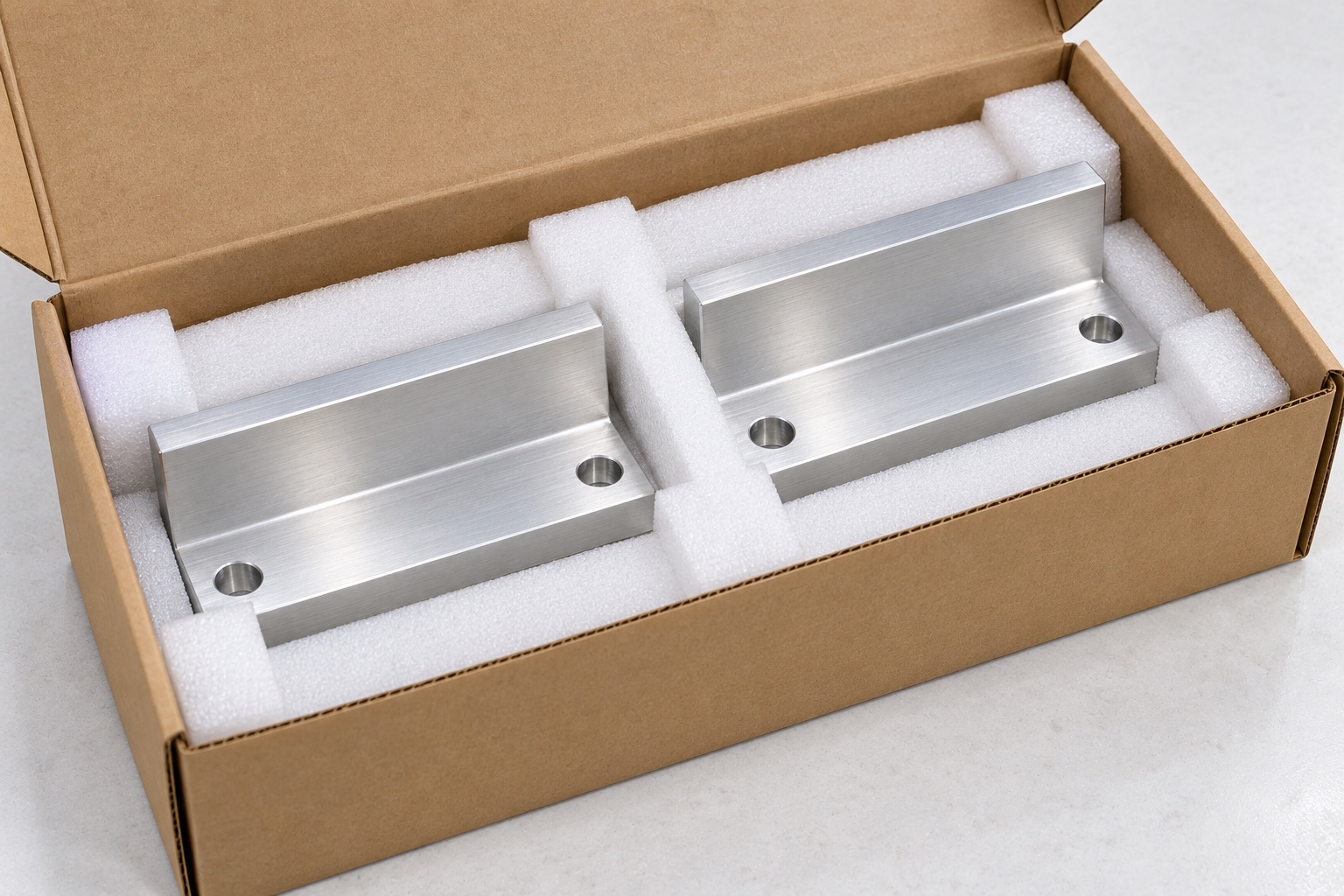
Protect accepted contacts during shipment
Separate finished jaws so adjacent edges and loose fasteners cannot strike the ledge or upright face. Support the stepped shape without bending it through packaging pressure. Keep unapproved adhesive and debris away from accepted contacts within the agreed cleaning scope. Protective packing is not sterile delivery. Preserve material lot, revision, treatment and acceptance status with the shipment. Receiving staff should distinguish released jaws from left-right variants, prototypes and altered trial pieces so the equipment team does not unknowingly mix different contact geometries before assembly and independent handling evaluation.
Build a plate-specific manufacturing package
Provide the controlled jaw model and drawing, exact plate and lid information, contact boundaries, mounting references, entry and release envelopes, material, final process and inspection deliverables. Identify any optional trial work separately from complete handling validation. Review changed plate variants, inserts, mechanism travel or cleaning requirements before repeating manufacture. Incorporate approved prototype changes into revised documents. This defines a traceable CNC scope without asking the supplier to invent clamp force or claim that an accepted aluminum contact jaw proves reliable transport, specimen integrity or analytical accuracy in an unspecified medical instrument.
Manufacturer background reference: www.thermofisher.com.
FAQ
Does plate format alone establish jaw compatibility?
No. The actual plate variant, skirt, lid and approved contact regions must be reviewed. A familiar footprint or empty plate fitting between jaws does not establish compatibility throughout entry, clamping and release in a complete medical analyzer mechanism.
Does this article specify a clamping force?
No. Actuator force, travel and permitted plate loading belong to the actual approved mechanism. Component geometry and material identity do not independently establish a universal safe force, holding capacity or resistance to plate damage during operation.
Can a contact pad be added during a trial?
Only through an authorized decision when it changes the controlled contact arrangement. Record the pad identity, geometry and installation conditions. An improvised insert should not become an undocumented production instruction or a substitute for evaluating the actual complete handling process.
Is a plate sample a complete inspection gauge?
Not automatically. It can support a defined fit observation with an identified revision. Drawing characteristics, contact relationships and final condition still require their agreed inspection methods; a favorable seating observation does not replace all dimensional acceptance criteria.
Does a smooth jaw prove a clean handling process?
No. Appearance does not establish measured particle generation, validated cleaning, sterile status or non-damaging contact. Any such requirements must be specified and evaluated for the actual surfaces, plate materials and complete medical analyzer application.
What changes require review on another order?
Review plate and lid variant, contact boundaries, ledge and face, mounting, inserts, mechanism travel, material and final treatment. Preserve controlled revisions instead of reproducing an altered trial jaw or transferring another plate configuration's handling and performance claims.

tanghangyun@oemach.com