
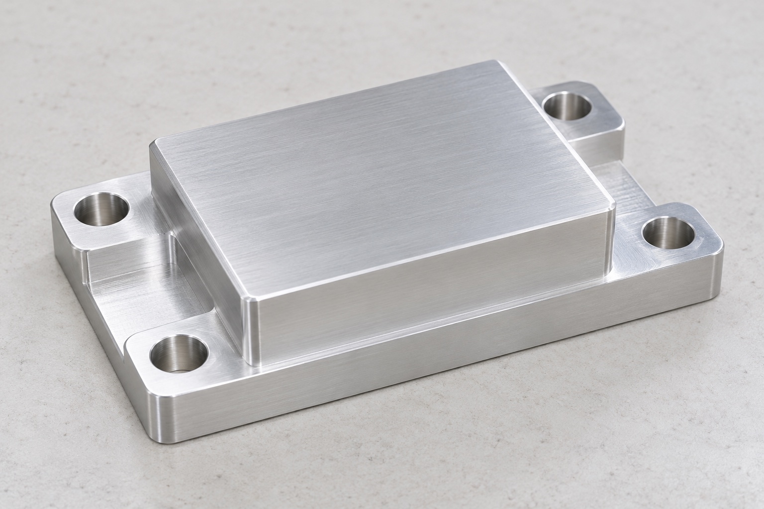
A mounting component is not a calibrated sensor
A medical analyzer may contain a load cell for an equipment-specific weighing or force-monitoring task. A machined support block connects that sensor installation to the surrounding structure. Its mounting land, base and fastener relationships need a controlled definition, but machining the block does not calibrate the sensor or validate an analytical result. This article addresses equipment-side CNC manufacture. It supplies no universal mounting dimensions, load capacity or medical performance claim. Illustrations show a proposed support concept, not measured production parts or a qualified weighing assembly.

Start with the exact sensor installation
Obtain the approved sensor model, mounting information, equipment drawing and installation orientation before selecting a support geometry. Different sensing arrangements do not necessarily share a load path or attachment method. Manufacturer guidance is background for reviewing the actual installation, not permission to substitute a generic block. Identify which surfaces contact the sensor and which belong to the surrounding frame. Clarify whether the support carries a sensor base, an intermediate adapter or another defined component, rather than inferring its role from a photograph or the sensor's external outline.
Map the intended load path
The equipment designer should identify where force enters and leaves the approved assembly, including any restricted contacts or required clearances. A support block should not create an unintended bridge around the sensing element. The machining supplier needs controlled geometry and relevant assembly envelopes, not responsibility for inventing the measurement architecture. Record unresolved contacts before releasing the drawing. A block that fits the available space may still change the intended arrangement, and an informal extra pad or washer should not become a solution without an authorized design review.
Relate the raised land to the base
Define the functional mounting land and base references explicitly, including their required relationship in the final component condition. A raised rectangular land is only a concept until its location, size and contact requirements are approved. The entire outer contour need not be a locating feature. Specify any allowed edge transition so a broad chamfer does not consume a required contact area. Resolve drawing and model conflicts before machining instead of treating whichever surface is easiest to hold as the reference for all subsequent measurements and installation decisions.
Keep attachment and positioning distinct
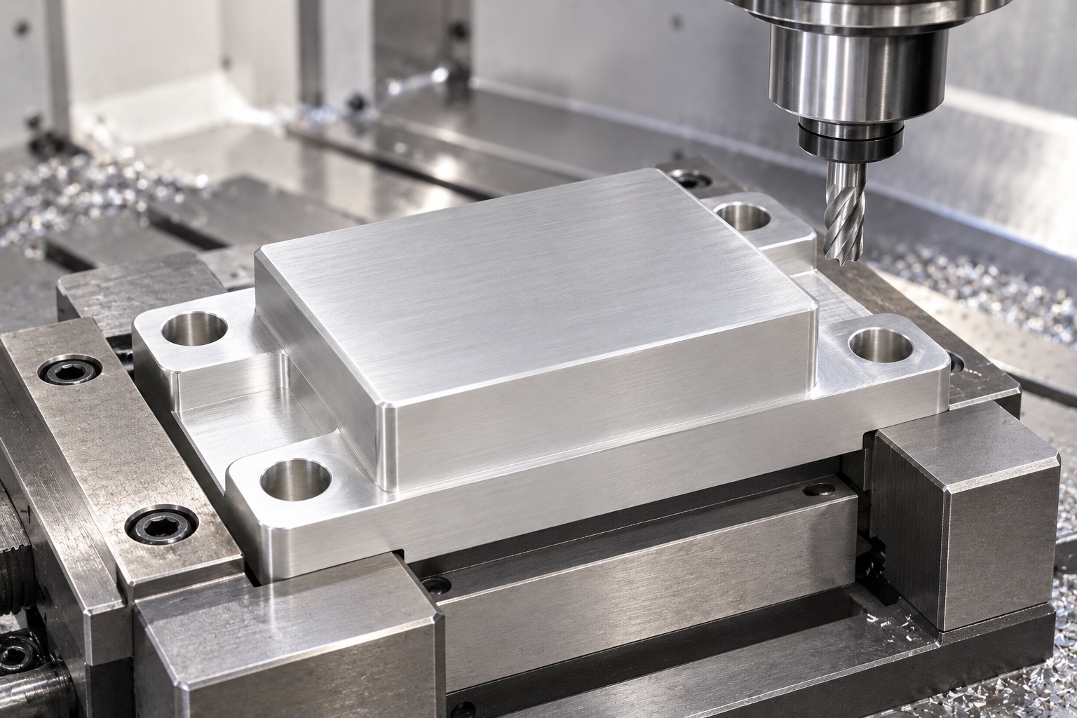
Clarify whether each mounting hole is a clearance feature, a threaded attachment or a controlled locator in the actual design. Do not assume that four screws accurately locate the sensor or block. Review tool access, screw head envelopes and any prescribed installation sequence with the real mating parts. The CNC supplier should not choose a universal tightening torque or enlarge holes until a sample fits. Such choices can change contacts or constraint, so they require documented approval rather than an undocumented adjustment during assembly or first-part inspection.
Specify material and the final condition
The order should identify aluminum grade, condition, stock form and required material documentation. A proposed 6061 support is not an assertion of sufficient stiffness for an unspecified load. Any coating, masking or other final process should be agreed with inspection in the relevant finished condition. Keep material lots traceable through machining and shipment. Appearance cannot establish strength, corrosion behavior or dimensional stability of the installed assembly. The responsible equipment team must evaluate material and surface choices against its actual load, environment and installation requirements before accepting substitutions.
Machine with support beneath functional regions
Plan blank preparation, roughing, finishing and fixture transfers around the base and raised land. Uneven material removal or excessive holding force can affect the component after release. Keep chips away from locating faces and provide support where the fixture actually contacts the workpiece. There is no universal cutting recipe or clamp force in this article. Intermediate checks can confirm the proposed sequence, but final inspection should address the agreed component condition rather than reporting only a surface made apparently flat while it is restrained against a fixture.
Protect land boundaries during edge finishing
Examine hole exits, outside corners and the step around the raised land for attached material or unwanted sharp features. Apply the released edge requirements without rounding away useful support or polishing the land to hide marks. Any allowed relief should be approved before manufacture. Cleaning follows the purchased scope and should preserve the finished references. A visibly clean block is not proof of sterile delivery, a quantified particle limit or validated chemical resistance. Subsequent handling and final processing must not silently change the contacts used in the inspection plan.
Inspect relationships in an agreed support state
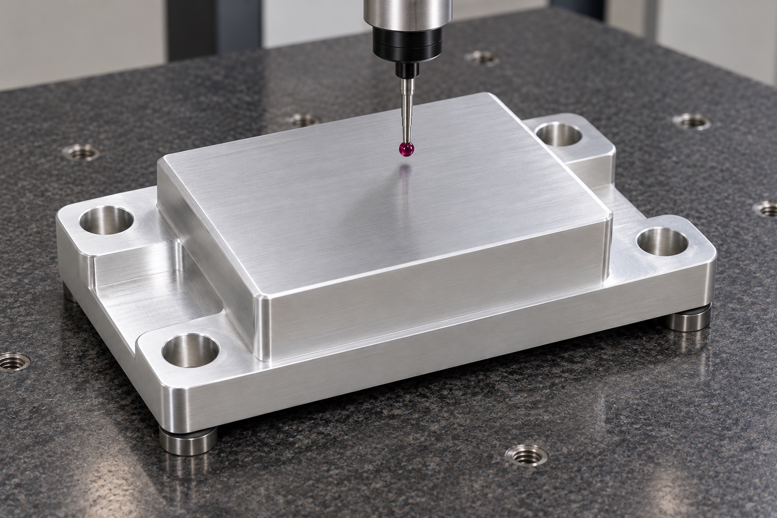
Link each controlled land, base, height and hole characteristic to a suitable measurement method and reference system. Identify whether final processing has occurred and how the component is supported during measurement. An outside-size report alone cannot verify a mounting arrangement governed by contact relationships. If a characteristic cannot be accessed reliably, clarify the method before production instead of substituting a convenient measurement. A sensor used for an optional fit demonstration is not automatically a dimensional gauge, and its electrical reading does not replace the block's drawing-based acceptance criteria.
Separate assembly observation from calibration
A defined trial may document seating, fastener access and required clearances with identified sensor and equipment revisions. Record the installation procedure and avoid transferring unknown forces through the sensor during assembly. Successful seating does not establish calibration, resolution, drift, overload resistance or medical analyzer accuracy. Those require separate procedures for the actual sensor and complete system. FUTEK's installation guidance emphasizes mounting conditions and load alignment, but does not qualify this proposed block or prescribe its dimensions. Keep component inspection and system-level measurement evidence as separate, traceable deliverables.
Package accepted faces without pressure damage
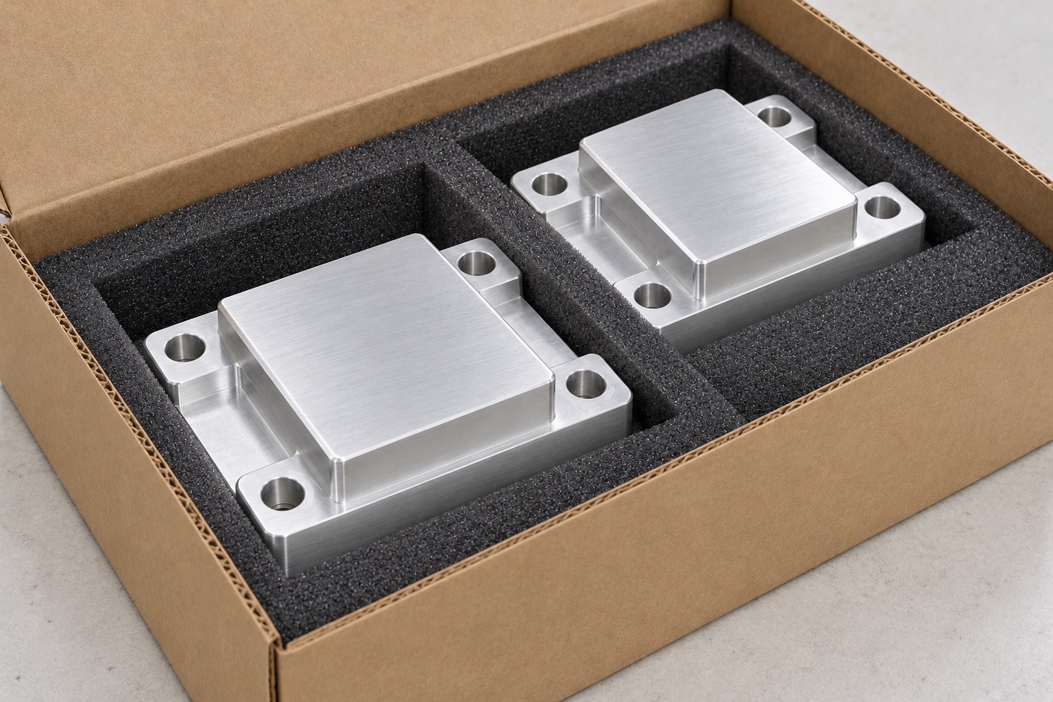
Separate finished supports so adjacent edges and loose fasteners cannot strike the mounting land or base. Packaging should protect the raised region without forcing the block into a distorted condition. Keep adhesives and debris away from defined contacts within the agreed cleaning scope. Ordinary protective packaging is not sterile packaging. Preserve revision, material lot, final process and acceptance status with the shipment so receiving personnel can distinguish released supports from prototypes, sensor-specific variants and hand-adjusted trial parts before they are placed into assembly stock for a medical instrument.
Maintain a sensor-specific inquiry record
A useful inquiry includes controlled geometry, exact sensor mounting information, equipment references, load-path intent, hardware, material, final treatment and inspection deliverables. Identify any optional assembly work and assign independent calibration or system testing explicitly. Review changes to sensor variant, support contacts, frame, fasteners or surface condition before repeating manufacture. Incorporate approved prototype changes into revised documents rather than copying an altered sample. This gives the CNC supplier a clear mechanical scope without implying that dimensional acceptance of an aluminum block proves the performance of a medical weighing or force-measurement system.
Manufacturer background reference: media.futek.com.
FAQ
Does machining the support calibrate the load cell?
No. Component machining and dimensional inspection establish only the agreed support characteristics. Calibration and performance evaluation require separate procedures for the identified sensor and complete installation, including its actual loading and environmental conditions.
Can one mounting block fit any load cell?
No. Sensor contacts, attachment, clearances, orientation and load path differ. Use the approved sensor and equipment documents; a similar outline or matching screws should not establish compatibility or authorize changes to the measurement arrangement.
Is the raised land automatically the locating datum?
Not automatically. The drawing must define functional references and contact requirements. The raised feature may support an intermediate component, and its relationship to the base and mounting pattern must follow the approved installation rather than the illustration.
Should extra washers correct a seating problem?
Only if authorized by the responsible designer. Record the observed interference and actual revisions first. Additional parts can alter contacts, constraint or the load path and should not become an undocumented production instruction for subsequent supports.
What can an optional installation trial show?
It can document agreed seating, fastener access and clearances with identified parts. It does not independently establish measurement accuracy, drift, overload resistance, calibration status or medical analyzer performance without separately defined procedures and evidence.
What should change control cover?
Review sensor variant, mounting information, load-path intent, support land and base, frame contacts, hardware, material and final treatment. Keep authorized revisions and inspection evidence together instead of transferring observations from another sensor arrangement or copying a hand-modified support.

tanghangyun@oemach.com