
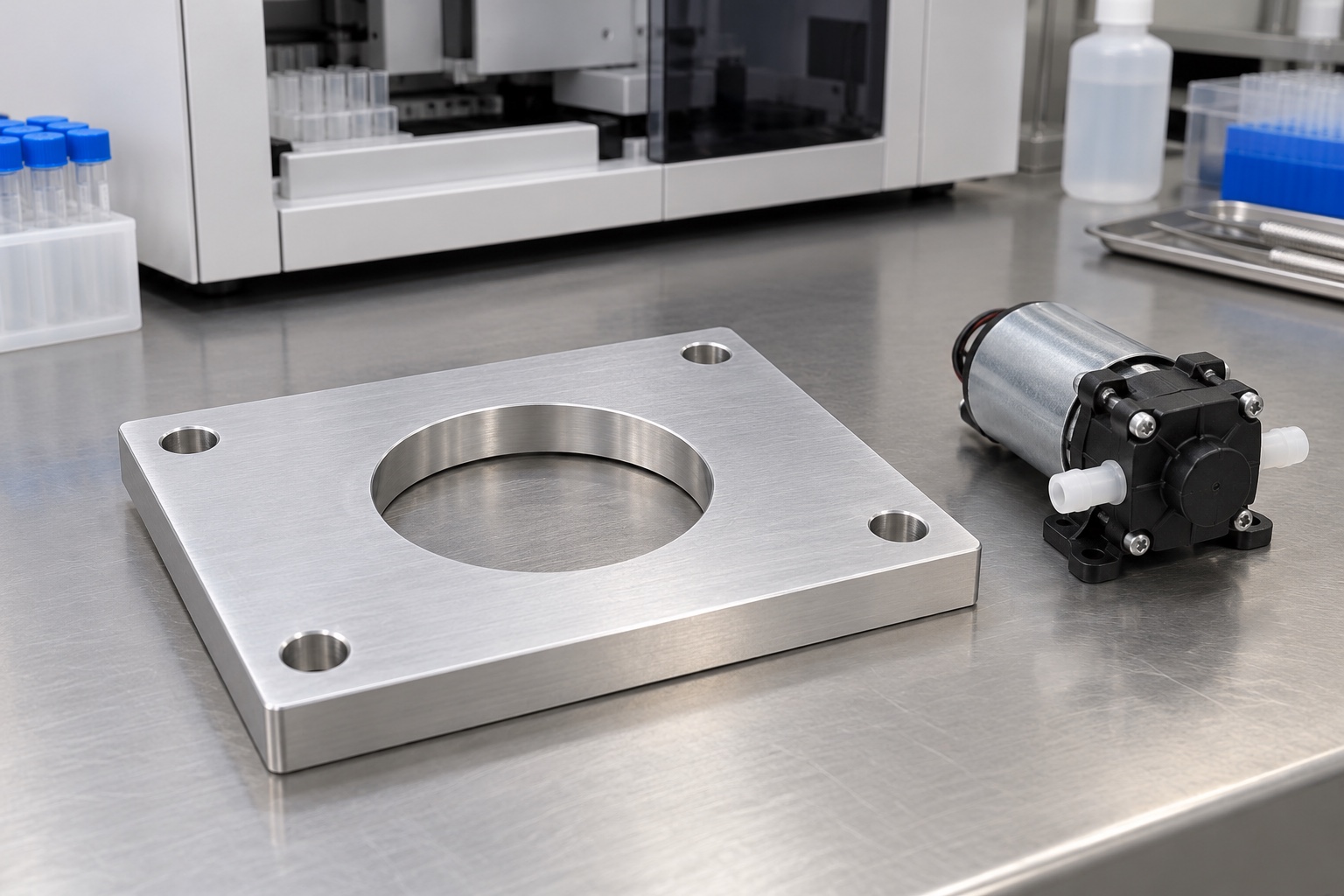
A mechanical interface outside the pumping path
A medical analyzer may use a machined plate to connect a miniature pump to its supporting structure. The plate establishes mounting contacts, clearances and access; it is not automatically a fluid-contact part or a pressure boundary. Its geometry should follow the actual pump and equipment documents. This article addresses CNC planning, inspection and handling. It does not prescribe universal mounting dimensions or demonstrate flow, leak tightness, vibration isolation or medical equipment safety. Images illustrate component concepts rather than measured production parts or a qualified pump installation.

Obtain the exact installation information
Identify the approved pump model, variant, mounting drawing and equipment revision before quoting the plate. Manufacturer installation information must be read for the actual selected product; the cited KNF manual is background, not a compatibility statement for this proposed geometry. Do not transfer another pump's mounting pattern or operating claims. Clarify which requirements belong to the plate and which belong to pump selection, tubing, electrical installation or the complete analyzer. An unlabelled pump sample cannot replace a controlled interface definition for repeat production.
Define contacts before hole positions
The plate may touch the equipment structure on one side and an approved pump foot or intermediate mounting arrangement on the other. Identify those contacts and the locating method explicitly. Distinguish clearance holes from features intended to locate. A photograph of four screws does not define the required reference system. Relate mounting patterns to the released contacts rather than a convenient raw edge. Resolve conflicting model and drawing dimensions before machining so the supplier does not choose a practical but functionally unrelated coordinate system for the installation.
Keep aperture function distinct from location
A central opening may provide mechanical clearance or service access, but its purpose must come from the approved design. Define its position, shape and edge requirements relative to the mounting references. Do not assume that the opening locates the pump, seals a chamber or carries a shaft simply because it is circular. Review remaining material and fastener access with the actual mating parts. Enlarging the opening to clear one sample is a design change when it alters controlled geometry, not an informal finishing decision.
Check service access and connected components
Review access for approved fasteners and required maintenance operations in the actual installed orientation. Tubes, connectors, cables and neighboring components should be represented by controlled envelopes rather than guessed routes. The machining supplier should not select tubing, relocate ports or modify a pump to make the plate fit. Document unexpected contact and obtain an authorized resolution. A plate that bolts into an empty frame does not prove that the complete pump installation can be assembled or serviced under the equipment team's required conditions.
Specify stock and final treatment
Identify the approved aluminum grade, condition, stock form and material evidence. Preserve lot identity through manufacture and shipment. If coating or another final process is specified, agree coverage, masking and final-condition inspection. Bare silver illustrations do not specify an untreated delivery. The responsible designer should review any effect of treatment on contacts and clearances. Material documentation and appearance do not establish vibration behavior, environmental resistance or quantified cleanliness of the finished mounting interface. Proposed substitutions need approval rather than automatic acceptance based on a similar-looking plate.
Plan support around the open center
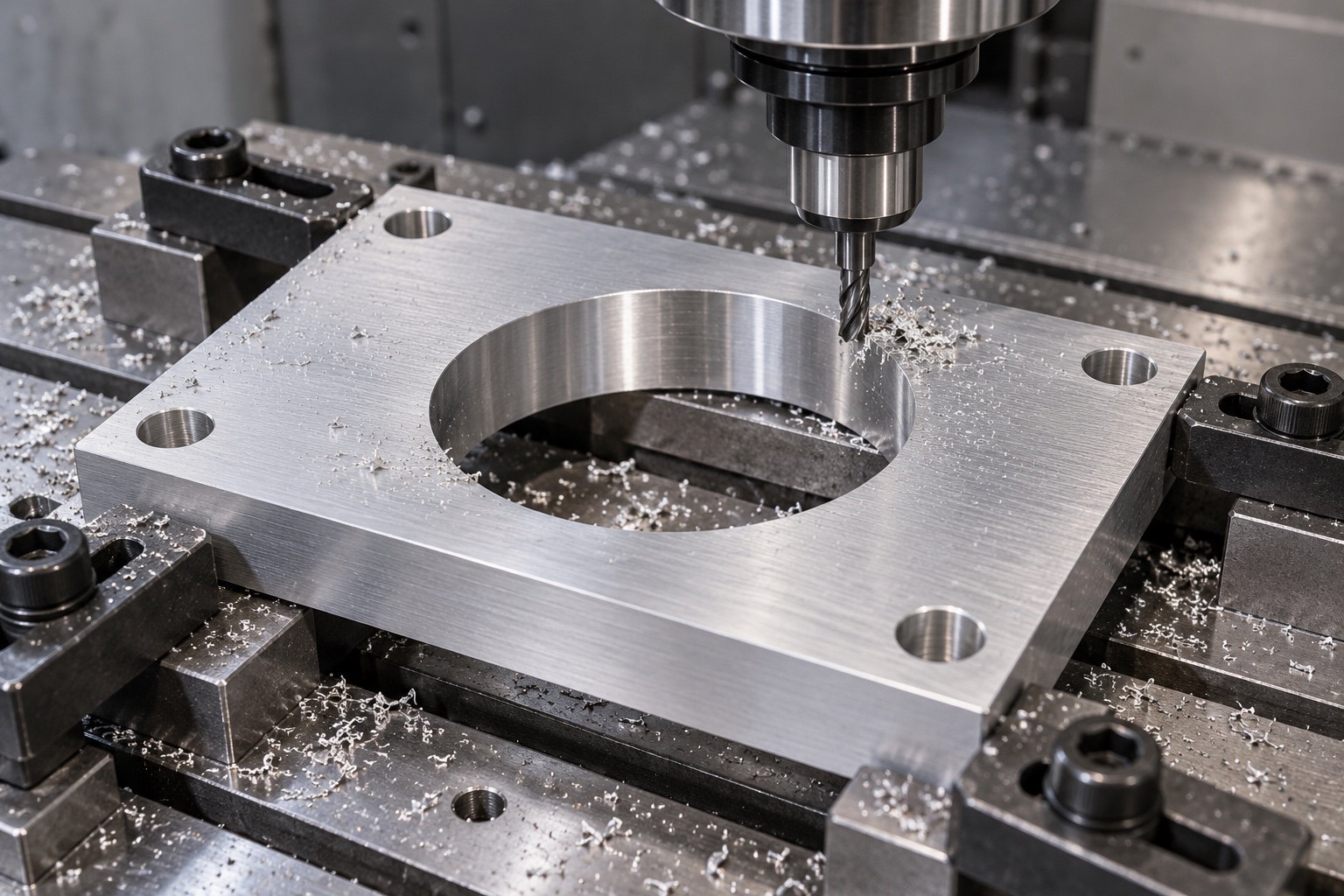
Removing a large central area changes the support of the remaining mounting lands. Review stock preparation, roughing, finishing and fixture transfers so the released contacts remain related after the plate is removed from the machine. Support solid regions and keep chips away from fixture faces. Avoid using excessive clamp force to make a distorted plate appear flat. There is no universal toolpath or cutting condition here. Intermediate checks may confirm the route but should not replace final inspection in the agreed component condition.
Finish edges without altering mounting lands
Inspect aperture edges, hole exits and outer boundaries for attached material or unwanted sharp features. Apply the approved edge requirements without broadly polishing the contact faces or changing useful support areas. Any permitted relief should be documented before production. Cleaning follows the purchased scope and must not conceal damaged contacts. A smooth-looking plate is not evidence of a sterile supply condition, a measured particle limit or successful corrosion testing. Later treatment and handling should preserve the same controlled geometry used for final acceptance.
Inspect functional relationships, not only outside size
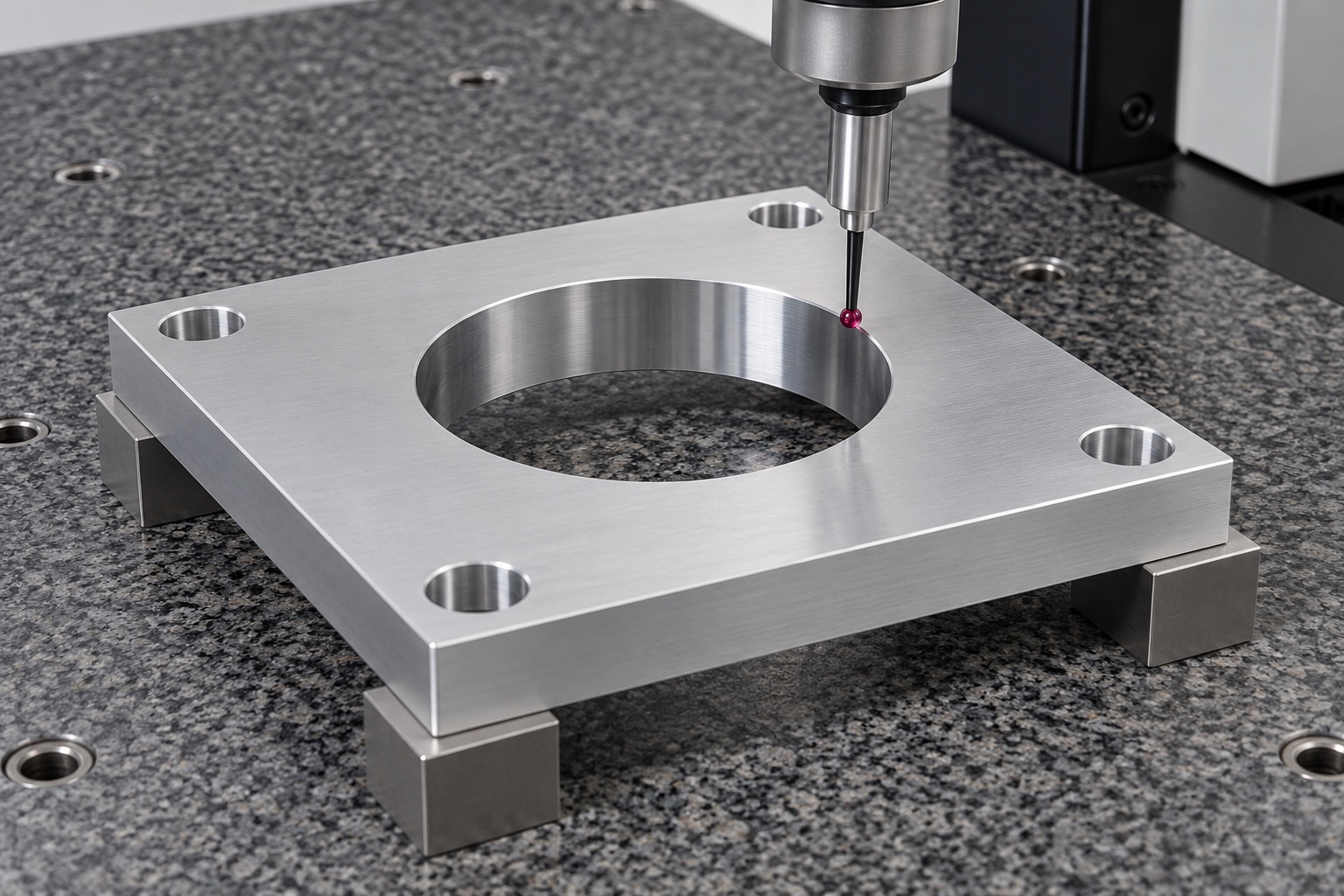
Map the drawing's contact, hole and aperture characteristics to suitable accessible methods using the approved references. Identify the relevant support state and final treatment. An outside rectangle and isolated hole diameters do not fully verify a mounting interface whose function depends on relative locations or contact geometry. Resolve inaccessible or ambiguous requirements before production instead of reporting easier unrelated measurements. Any check with the actual pump should have an explicitly agreed scope and remain traceable alongside, rather than silently replacing, required component inspection.
Separate a fit demonstration from pump qualification
An agreed mechanical trial may check seating, fastener access, aperture clearance and identified connected-component envelopes. Record pump, plate, equipment and hardware revisions with the installation conditions. A successful fit does not establish pump delivery rate, pressure, leakage, vibration, noise, electrical safety or analyzer performance. Those need separately defined evaluations for the actual assembly. Do not introduce an unapproved isolator, adhesive or washer to obtain a convenient demonstration. Keep trial components distinct so a hand-adjusted plate does not become the undocumented production master.
Protect accepted contacts in transport
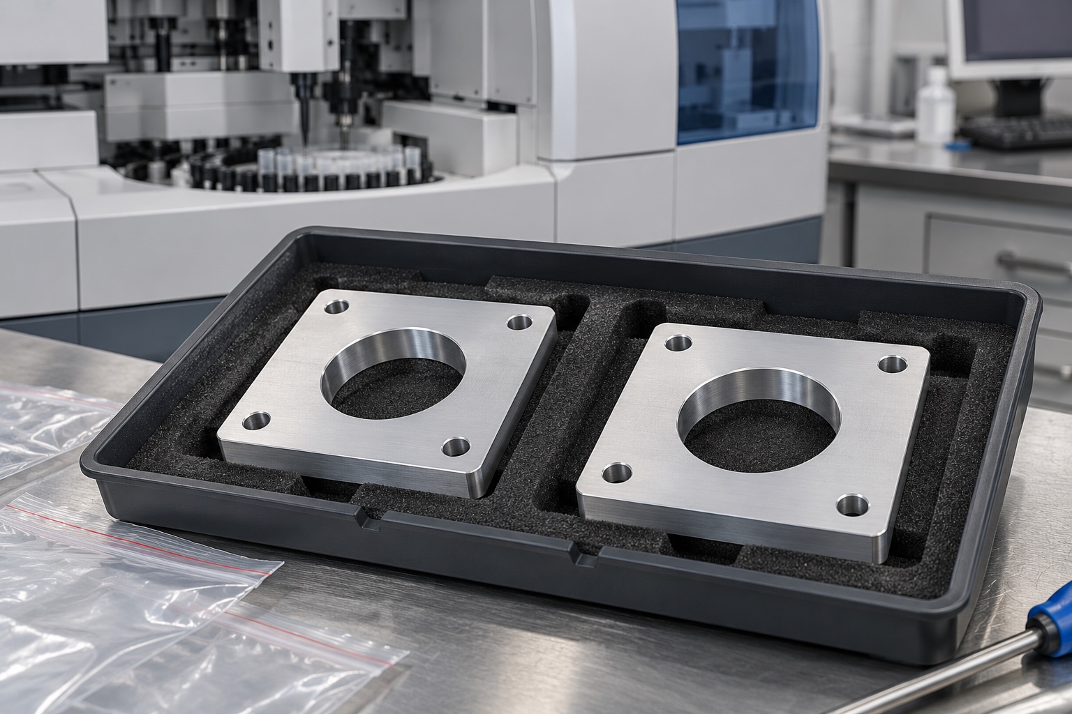
Separate finished plates so edges, fasteners and neighboring parts cannot rub the mounting lands or aperture. Support the remaining structure without bending it through packaging pressure. Keep unapproved adhesive and debris away from contacts within the agreed cleaning scope. Ordinary transport bags do not imply sterile delivery. Preserve material, final process, lot and revision identification with the shipment. Receiving personnel should distinguish accepted production from prototypes and similar plates intended for different pump variants, mounting arrangements or equipment configurations before they enter assembly stock.
Maintain a complete pump-specific inquiry
The inquiry should include the controlled model and drawing, exact pump installation documents, equipment contacts, connected-component envelopes, material, final process and inspection deliverables. Identify optional fit work and keep independent pump or system qualification separate unless expressly included. Incorporate authorized prototype changes in revised documents. Review changed pump variants, fasteners, isolators, tubing access or support structures before reusing earlier observations. This gives a CNC supplier a traceable mechanical scope without asking it to invent mounting requirements or claim that plate acceptance validates a medical analyzer's pumping performance.
Manufacturer background reference: knf.com.
FAQ
Is the mounting plate a fluid manifold or pressure part?
Not in this proposed scope. It is an equipment-side mechanical interface. Any fluid-contact, sealing or pressure-boundary function would require separate controlled requirements and evaluation rather than being inferred from a central aperture or the plate's proximity to a pump.
Does a matching hole pattern prove pump compatibility?
No. Contacts, aperture clearance, hardware, orientation and connected-component access also need definition. Use the exact pump and equipment documents; a successful loose assembly does not establish full installation compatibility or operating performance.
Can the central opening be enlarged after a trial?
Only through an authorized change when controlled geometry is affected. Record the pump and plate revisions, interference location and installation condition before modifying the design or turning a hand-adjusted sample into a production instruction.
Do the images prescribe a bare aluminum finish?
No. They illustrate geometry. The order defines material condition, treatment, masking and final inspection state. Any impact on contacts, clearances or the complete installation needs review under the actual approved requirements.
What can a mechanical fit demonstration establish?
It can document agreed seating, fastener access and clearances with identified components. It does not independently qualify flow, pressure, leakage, vibration, noise, electrical safety or medical analyzer performance without separately specified procedures and evidence.
What should be reviewed before repeating manufacture?
Review pump model and variant, mounting contacts, aperture, connected-component envelopes, hardware, isolators, material and final process. Preserve authorized revisions rather than copying an undocumented prototype or transferring results from another installed pump arrangement.

tanghangyun@oemach.com