
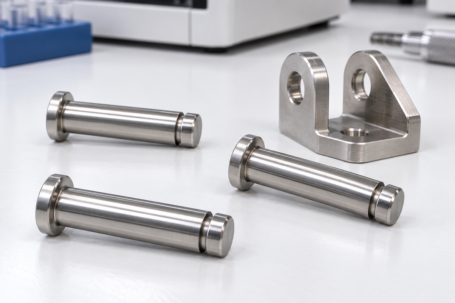
A pin interface rather than a complete joint
A grooved pivot pin can locate a moving member in a medical equipment mechanism while a separately specified external retaining ring controls axial retention. The smooth journal, integral head and ring groove have different functions. Their geometry should follow the actual joint rather than a generic pin photograph. This article addresses CNC turning and component inspection, not a universal bearing fit, rated load or fatigue life. Illustrations are representative concepts, not delivered parts, and dimensional acceptance does not by itself validate a complete medical equipment joint.

Start with the selected ring and mating stack
Identify the exact retaining-ring type, manufacturer information, mating components and intended movement before defining the pin. Smalley's selection guidance identifies shaft and groove dimensions as relevant inputs; it is background rather than approval of this custom assembly. An external ring seat is not interchangeable with an internal housing-ring groove. Resolve ring identity and installation requirements with the responsible designer. A ring that can be pushed onto a sample should not establish all groove limits, service loads or suitability for the medical equipment mechanism.
Separate the journal from retention geometry
The journal diameter, useful length, form and surface requirements depend on the approved mating bore and intended movement. The ring groove has its own diameter, width, location, flank and root requirements. Neither feature should be inferred solely from overall pin length. Identify which surfaces contact the mating parts and where clearances are required. The supplier must not transfer the nominal journal size into an assumed ring-seat dimension or use a generic catalog pin as a replacement for a controlled joint drawing.
Control the axial relationship from functional contacts
Relate the underside of the head, useful journal and retaining-ring seat to the actual mating stack. Distinguish intended axial freedom from clamping or retention contacts. A ring may appear installed even when its relationship to the mating parts is not correct. Specify the relevant references and inspection scope instead of relying on total length alone. Extra washers, a deeper groove or a thinner head are not informal adjustment tools. Any proposed change must be reviewed against the released assembly and incorporated through authorization.
Specify the material condition without borrowing ratings
If 316L stainless steel is selected, state the required condition, stock form and material evidence. Preserve lot identity through turning and final processing. A stainless appearance does not establish equivalence to another pin, ring or strength-rated product. The responsible design program should evaluate load, environment and service conditions separately. The CNC supplier should not borrow a catalog ring's rating for an arbitrary pin and groove material. Any change to material or treatment needs review before the manufacturing route and final acceptance requirements are fixed.
Plan turning around the journal reference
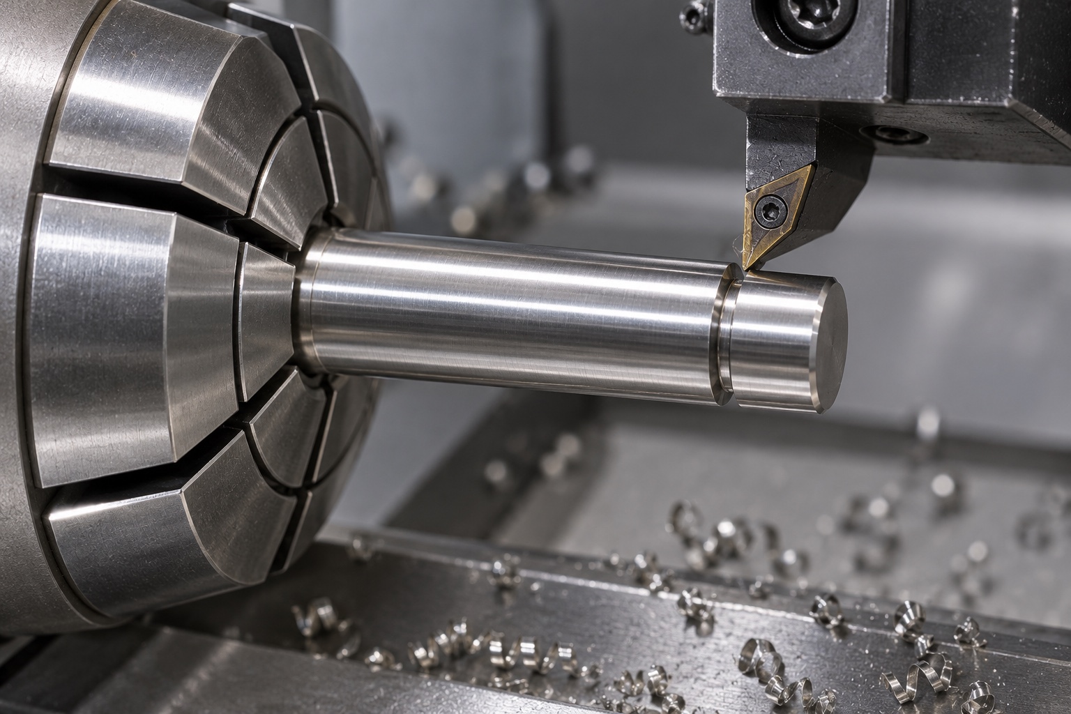
Choose workholding and setup transfers that preserve the required relationship between head contact, journal and groove. Review access to the groove before production and protect finished cylindrical surfaces during later operations. Keep chips off collet contacts and avoid excessive holding force that distorts a slender part. Intermediate checks can confirm the route but are not a substitute for final inspection. There is no universal tool geometry or cutting condition here, and a manufacturing convenience must not change the approved groove root or useful journal length without authorization.
Keep groove edges and roots within the definition
Examine the groove flanks, root, adjacent journal and end chamfer for attached material or unwanted sharp features. Finishing should preserve the specified seat rather than round it until a ring seems easy to install. Tool access and any allowed root radius need prior review against the selected retaining arrangement. Do not add a cross hole, thread or alternate retention feature without approval. Visible smoothness is not evidence of correct groove geometry, ring seating, fatigue performance or safe retention under the actual mechanism's operating conditions.
Measure the seat with an appropriate method
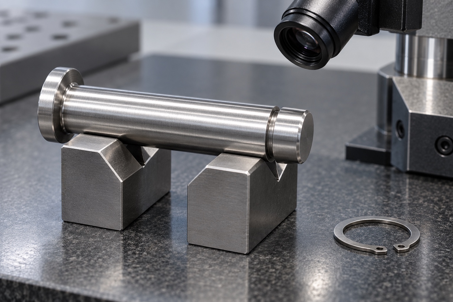
Map groove diameter, width, location and other drawing characteristics to suitable accessible inspection methods. The measuring contact or optical system must resolve the narrow feature rather than bridge its edges and report an unrelated size. Identify journal and head references and record the final condition. A micrometer reading on the smooth shaft alone cannot verify the ring seat. Clarify ambiguous measurements before manufacture; a ring-fit demonstration should not silently replace the released dimensional requirements or a difficult inspection that has not been planned.
Treat final processing as part of acceptance
Any specified passivation, coating or other treatment needs controlled documentation and relevant final-condition checks. Cleaning should follow the purchased scope and protect the groove and journal from manufacturing debris. Do not add unapproved oil or polish to obtain a satisfactory demonstration. A bright surface does not establish corrosion performance, quantified cleanliness, sterile supply or a measured friction value. Material and dimensional evidence support their own acceptance scope, while environmental and mechanism evaluations require separately defined conditions and records for the actual medical equipment installation.
Separate seating checks from retention qualification
An agreed assembly trial may check insertion, head contact, visible ring installation and intended axial movement using identified components and procedures. It does not independently establish thrust capacity, impact resistance, fatigue life, ring disengagement behavior or equipment safety. Those require their own specified evaluations. A hand-operated trial is not a working-load test. Keep ring identity, mating stack and any authorized lubrication traceable. Unexpected seating or movement should be resolved before changing the pin, rather than hidden with substitute rings or undocumented washers.
Protect journals and groove edges in transit
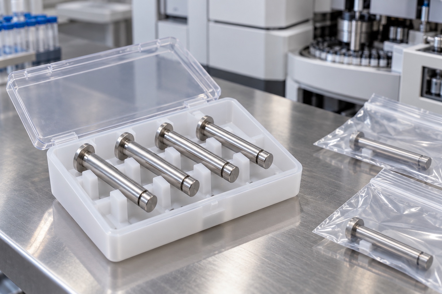
Separate pins so heads and groove edges do not strike accepted cylindrical surfaces. Support slender journals without bending them under packaging pressure. Keep loose rings and hardware separate and identified. Protective materials should match the agreed cleaning scope, and ordinary bags should not imply sterile delivery. Preserve material, lot, treatment and revision identity with the shipment. Receiving personnel should be able to distinguish released pins from prototypes and superficially similar fasteners intended for a different ring family, journal length, groove location or mating assembly.
Preserve the entire joint-specific baseline
A useful inquiry includes controlled pin geometry, exact ring documents, mating stack, movement requirements, material condition, final processing and inspection deliverables. Identify optional assembly demonstrations and keep strength or retention qualification separate unless explicitly purchased. Review changed rings, bores, stack thicknesses, journal contacts, lubrication and treatment before relying on previous observations. Retain authorized changes instead of copying a hand-adjusted sample. This defines a traceable CNC component without asking the supplier to invent a medical mechanism rating or claim that a seated retaining ring proves joint safety.
Manufacturer background reference: www.smalley.com.
FAQ
Does a seated retaining ring prove the joint load rating?
No. Seating and geometry are distinct from load and retention qualification. The selected ring, groove material, mating arrangement and operating conditions need separately defined evaluation before any capacity or safety claim is made.
Can an internal-ring groove define an external pin seat?
Not automatically. Ring family, shaft or housing arrangement and manufacturer's requirements must match the approved assembly. A nominal size or a visually similar ring should not replace the controlled groove definition.
Why is overall length insufficient?
The functional relationship depends on head contact, useful journal, groove location and the actual mating stack. A correct total length can coexist with an incorrect ring seat or axial relationship, so those controlled features require their own inspection.
May the groove be widened to improve assembly?
Only after authorization. First identify the actual ring and mating revisions and document the problem. Informal widening or rounding can change the retention interface and should not become an undocumented production instruction.
Does 316L imply a high-strength standard pin?
No. Material identity and appearance do not establish another product's properties or rating. The actual condition, geometry and service requirements need approval, with strength and fatigue evaluation separate from CNC dimensional acceptance.
What should change-control review include?
Review ring identity, mating bore and stack, journal and groove geometry, material, final process and lubrication. Retain controlled revisions rather than transferring observations from another joint or reproducing an adjusted prototype as the master.

tanghangyun@oemach.com