
Built-up edge is material that adheres to the cutting edge under pressure and friction. In copper machining, the deposit changes the effective tool geometry, breaks away unpredictably and can smear or tear the finished surface. It may also increase burrs and move a precision dimension.
The problem is not solved by changing spindle speed alone. Copper alloy, temper, tool sharpness, edge preparation, chip load, coolant direction, tool overhang and chip evacuation all interact. Pure copper and oxygen-free copper are generally more prone to adhesion than many free-cutting brass grades because of their higher ductility.
A useful troubleshooting process starts by confirming the exact material, then inspecting the cutting edge and chips before changing multiple parameters at once.
Troubleshooting built-up edge in copper machining
| Check | Risk signal | Corrective direction |
|---|---|---|
| Material condition | Soft, highly ductile copper smears easily | Confirm alloy, temper, hardness and incoming surface |
| Cutting edge | Wear, edge hone or deposited copper | Use a sharp polished rake face and replace the tool before rubbing begins |
| Chip load and heat | Rubbing, dwell or unstable engagement | Maintain a real cutting load and adjust speed/feed as a pair |
| Chip evacuation | Chips recut in slots, pockets or holes | Use directed coolant or air, shorter engagement and staged chip removal |
| Surface and burrs | Smearing, torn finish or heavy edge burr | Stabilize cutting first, then define controlled deburring |
How Built-Up Edge Develops
At the contact zone, high pressure and friction can make ductile copper adhere to the rake face. The deposit grows, acts like an irregular cutting edge and later detaches. Each cycle changes cutting force and surface generation, which is why a part may alternate between a bright finish and dragged marks.
A dull tool or excessive edge radius promotes rubbing instead of shearing. Too little chip load, dwelling in a corner, excessive tool overhang or poor rigidity can make the contact less stable. Trapped chips then scratch the surface again, especially in deep grooves, small holes and threads.
Start With Tool Geometry And Edge Condition
A sharp tool with a polished, low-friction rake face is usually the first requirement. Tool material and coating must suit the alloy and operation; the useful principle is to avoid a rough or heavily honed edge that pushes soft copper before cutting it.
Inspect the edge under magnification and compare it with chip shape and surface marks. If copper has welded to the rake face, cleaning or replacing the tool and correcting the cause is more reliable than compensating dimensions around a damaged edge.
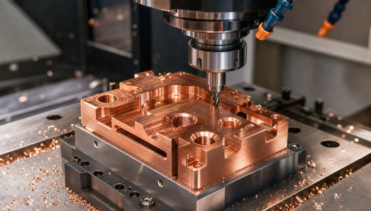
Sharp cutting geometry, stable chip load and directed coolant help prevent rubbing, adhesion and chip recutting on ductile copper.
Control Chip Load, Cooling And Evacuation Together
Feed and speed should be adjusted together so the cutter shears material instead of rubbing. A stable chip load, limited dwell and controlled engagement usually matter more than chasing one universal spindle speed. Starting values should come from the tool supplier and be proven on the actual alloy and setup.
Coolant or air must reach the cutting zone and move chips away. For deep slots, holes and threads, reduce unnecessary tool extension, use staged cutting or pecking, and clear chips before they are recut. Any cleaning requirement for electrical contact parts should be included in the process plan.
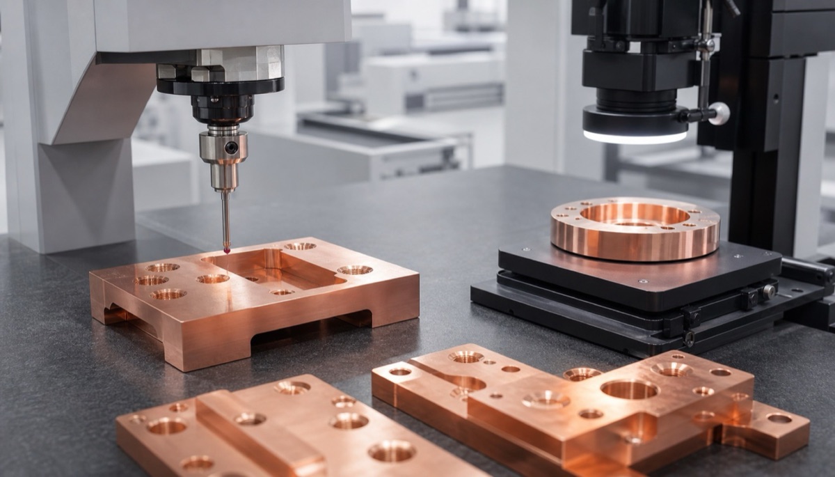
After the cutting process is stabilized, verify functional dimensions, surface condition, burr limits and cleanliness rather than relying on polishing.
Information To Confirm Before Machining
Brass is often easier to cut than pure copper, but alloy-specific behavior still matters. Thin walls and multi-face features also require fixture and stress control independent of the adhesion problem.
In one copper contact and housing project, polished cutting edges, directed coolant and staged chip evacuation were combined with reusable inspection records. This approach helped improve yield by about 30 percent by preventing damage at the cutting stage rather than relying on cosmetic correction afterward.
- Exact copper alloy, temper and hardness condition
- Roughness requirements for electrical, sealing and cosmetic faces
- Depth and chip-clearance space of slots, holes and threads
- Permitted coolant residue and required cleaning method
- Defined burr limits, edge break and deburring method
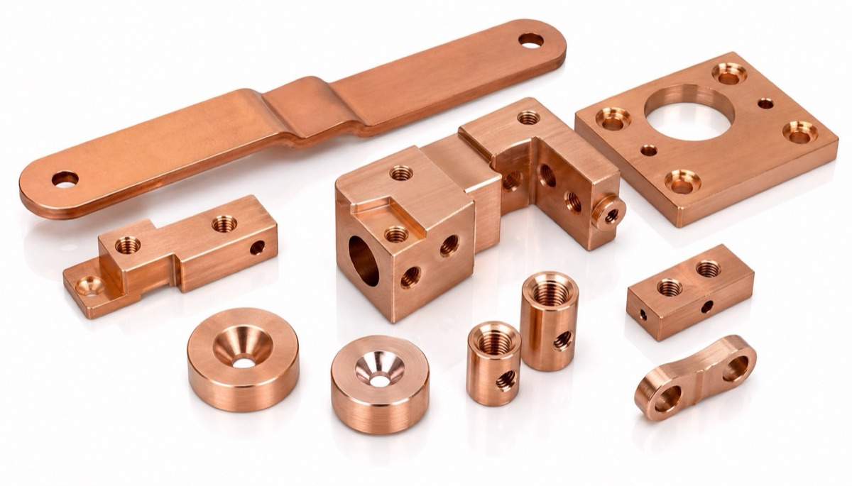
Alloy grade, temper and feature geometry determine tooling, chip evacuation, deburring and cleaning requirements.
Why Polishing Is Not The Primary Fix
Light polishing may improve a superficial mark, but it also removes material and can change edge geometry, flatness or a precision fit. It cannot reliably repair dimensions shifted by an unstable cutting edge.
The durable solution is to stabilize shearing and chip evacuation, then apply a controlled deburring or finishing operation with a measurable stock-removal limit. Functional surfaces should be reinspected after any corrective finishing.
Summary
Built-up edge in precision copper machining is a system problem involving material ductility, tool condition, cutting load, heat and chip evacuation. Confirm the alloy, use a sharp polished edge, maintain stable cutting, direct coolant to the contact zone and prevent chip recutting before adjusting cosmetic finishing.
FAQ
Can pure copper use the same parameters as aluminum?
It is not recommended. Copper has different ductility, thermal behavior and adhesion tendency, so speed, feed, edge geometry and coolant delivery should be validated again.
Can polishing repair a dragged copper surface?
It may improve light marks, but it removes material and can affect dimensions or edges. The root cause should be corrected in cutting and chip evacuation.
Does higher spindle speed always prevent built-up edge?
No. Speed, feed, engagement, edge condition and coolant must work together. Higher speed without a stable chip load can still produce rubbing or heat.
Which features are most vulnerable to chip recutting?
Deep slots, blind pockets, small holes and threads where chips cannot leave the cutting zone easily.
Ready to get a quote for your CNC machined parts?
Submit your engineering drawings to qiancj@oemach.com. We support prototype sampling and small-batch production with strict tolerance control.