
Standard anodizing and hard anodizing both build an oxide layer on aluminum, but they solve different engineering problems. Standard anodizing is commonly selected for appearance, color identification and moderate corrosion protection. Hard anodizing is selected when sliding contact, wear resistance or electrical insulation is more important.
Hard anodizing is not automatically the better specification. Its thicker layer creates more dimensional change, can increase edge brittleness and usually costs more. Precision bores, bearing seats, threads and grounding faces need a clear masking, allowance or post-machining plan.
For robot components, choose the finish from the contact condition and assembly function, then define coating thickness, sealing, color, inspection and protected surfaces on the drawing.
Standard anodizing and hard anodizing compared
| Item | Typical thickness | Best use | Dimensional consideration |
|---|---|---|---|
| Standard anodizing | 5 to 20 micrometers | Appearance, color coding and moderate corrosion resistance | Lower compensation, but fits still need review |
| Hard anodizing | 25 to 50 micrometers | Wear, insulation and sliding contact | More allowance and masking are normally required |
| Precision bores and bearing seats | Often uncoated or selectively coated | Preserve fits and datum accuracy | Mask, leave allowance or finish after coating |
| Threads and electrical contact faces | Specified by function | Prevent seizure or maintain conductivity | Mask threads or chase them only under a controlled plan |
Choose The Finish From The Contact Condition
A bushing seat, slider, guide contact or frequently rubbed surface may justify hard anodizing. A housing, cover, non-friction bracket or color-coded component often needs only standard anodizing. Corrosion environment, cleaning chemicals, appearance and conductivity must be considered together.
Hard anodizing can be useful for wear but is not a substitute for correct bearing or bushing design. It can also crack more easily at sharp edges or under local deformation. Edge breaks, radii and contact pressure should therefore be reviewed before the coating is specified.
Plan Dimensional Change Before CNC Machining
An anodic layer grows partly into the aluminum and partly outward from the original surface. The exact ratio depends on alloy, bath and process. This means a coated bore may become smaller and an external feature may become larger. A blanket compensation value should not be assumed without the coating supplier's process data.
Drawings should identify coating-free bearing seats, dowel holes, threads, mounting datums and electrical contact faces. Depending on function, these areas can be masked, machined with allowance or finished after anodizing. The selected method should also consider whether post-machining exposes bare aluminum.
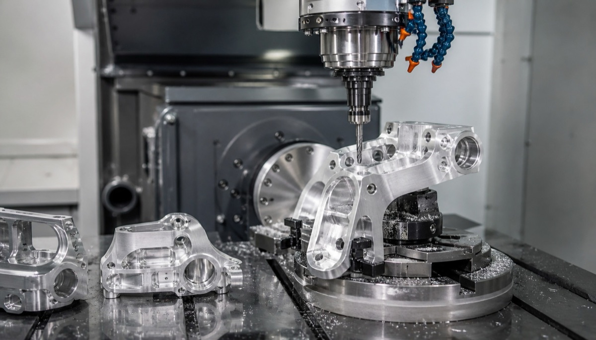
Material condition, critical fits and surfaces to be masked should be fixed before machining allowances are finalized.
Inspection Must Continue After Anodizing
A part that passes machining inspection can fail after coating because of layer growth, racking marks, sealing residue, trapped chemicals or handling damage. Reinspect critical fits, threads and mating surfaces after anodizing, and define where thickness or hardness is measured.
Color should be controlled with an approved sample and an agreed viewing condition. Alloy and heat-treatment differences can change color, so a black appearance alone does not confirm that a part has received hard anodizing.
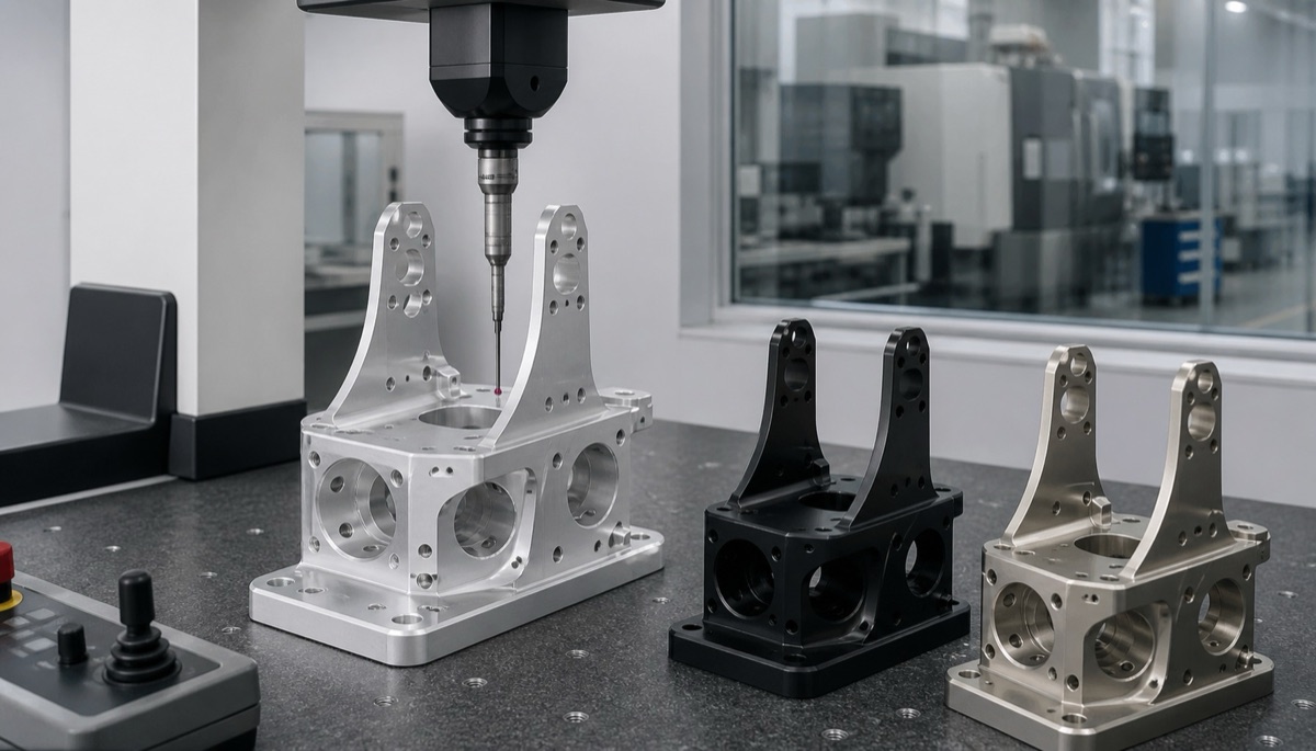
Post-anodizing inspection should focus on bores, threads, mating faces and geometric features affected by coating or handling.
Information To Confirm Before Ordering
In one aluminum robot-part project, masking precision mating surfaces, reserving coating allowance and repeating critical inspection after anodizing helped improve yield by about 30 percent. Reusable process records also reduced uncertainty on repeat orders.
- State the aluminum alloy and temper, such as 6061-T6 or 7075-T6.
- Identify sliding contact, wear, electrical insulation and corrosion requirements.
- Specify coating type, thickness range, color and sealing requirement.
- Mark precision bores, threads, datums and electrical faces that need masking or compensation.
- Define post-coating inspection and appearance acceptance with a sample when necessary.
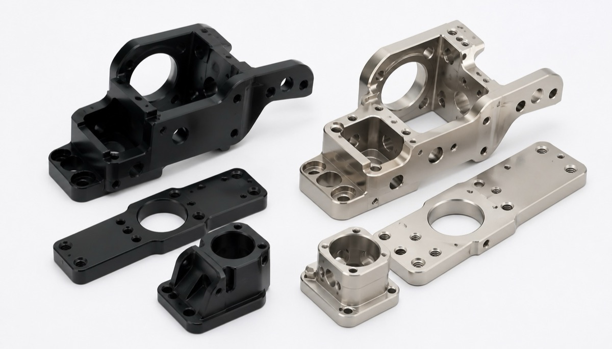
Color alone does not identify coating performance; thickness, sealing, hardness and masking requirements should be stated on the drawing.
Common Anodizing Specification Mistakes
The first mistake is specifying hard anodizing only because it sounds more durable. If the part has no meaningful wear or insulation requirement, standard anodizing may give better appearance with less dimensional risk and lower cost.
The second mistake is defining only a color. The drawing should state coating standard or type, thickness, sealing, masking and inspection. The third is waiting until after machining to discuss fits; by then there may be no material allowance for correction.
Summary
Use standard anodizing for appearance, identification and moderate corrosion protection. Use hard anodizing where wear or insulation justifies the additional thickness and dimensional risk. Define masking, allowance and post-coating inspection before machining starts.
FAQ
Is hard anodizing always better for robot parts?
No. It costs more and creates more dimensional change. It is worthwhile when wear, sliding contact or insulation requirements clearly justify it.
Why can a bore become smaller after anodizing?
The oxide layer grows partly outward from the original surface, reducing the available diameter. The drawing should define masking or machining compensation.
Should bearing seats and threads be anodized?
Not automatically. Precision fits and threads are often masked, compensated or selectively finished according to their assembly function.
Can black color prove that a part is hard anodized?
No. Color is not proof of thickness or hardness. The coating specification and inspection record should identify the actual process.
Ready to get a quote for your CNC machined parts?
Submit your engineering drawings to qiancj@oemach.com. We support prototype sampling and small-batch production with strict tolerance control.