
A robot repeatability specification of 0.01 mm describes how consistently the end effector or a joint returns to a commanded position under defined conditions. It is a system-level result, not a direct tolerance requirement for every machined feature.
The practical task is to divide the error budget among the reducer, bearings, transmission backlash, locating features, assembly datums, structural deformation and measurement repeatability. Applying +/-0.005 mm to an entire part usually adds cost without improving the robot in proportion.
For a useful drawing review, start with the functional chain. Identify which holes and faces locate the reducer, bearings, sensors and joint axes, then assign machining and inspection requirements to those features.
Typical tolerance priorities for robot precision parts
| Feature | Typical requirement | Process and inspection focus |
|---|---|---|
| Locating pin or bearing bore | +/-0.005 to +/-0.01 mm | Finish boring or reaming; verify size, position and coaxiality by CMM |
| Reducer mating face | Flatness 0.005 to 0.01 mm | Finish in one datum setup and control clamping stress |
| Connection hole pattern | Position 0.02 to 0.05 mm | Machine from a common datum and verify by CMM or a functional gauge |
| External clearance geometry | Around +/-0.1 mm | Keep a practical tolerance unless the surface locates another component |
Start With The Functional Error Chain
First-level features normally include bearing bores, locating pin holes, reducer mounting faces and sensor mounting surfaces. Their errors can change axis alignment, preload or feedback. Connection holes and external clearance areas can often use second- or third-level tolerances.
The robot's 0.01 mm value also includes components the machine shop does not control alone. Reducer backlash, bearing clearance, assembly force, temperature, controller compensation and test method all influence the measured endpoint result. The drawing should therefore specify the part characteristics that can actually be manufactured and verified.
Choose A Process Route That Protects Datums
A common datum should carry through rough machining, semi-finishing, finishing and CMM inspection. Fine boring, reaming or grinding may be used for critical bores. Multi-face hole systems, deep cavities, thin walls or curved structures may benefit from 5-axis machining because fewer setups reduce accumulated position error.
Thin-wall components may require soft jaws, vacuum support or profile fixtures. Stress-sensitive structures are often more stable when material is removed in stages, followed by stabilization and final finishing. The important point is not the number of axes by itself, but whether the route preserves the defined datum chain.
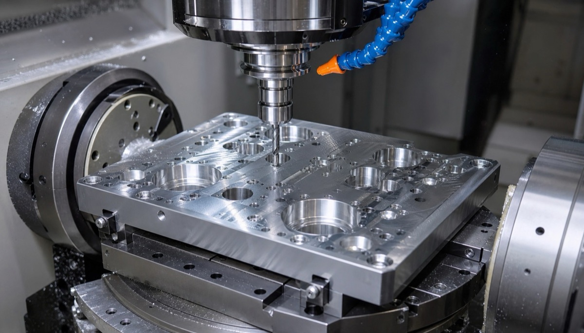
Critical hole patterns and mating faces should be machined from a controlled datum with as few reclampings as practical.
Grade Tolerances Instead Of Tightening Everything
Use +/-0.005 mm only where the functional stack and process capability justify it. Other key locations may use +/-0.01 mm or +/-0.02 mm, while non-functional clearance dimensions can be looser. This grading leaves inspection effort where it affects assembly and motion performance.
A supplier should explain the expected process capability, measurement uncertainty and temperature conditions. A nominally tight dimension is not useful if the inspection method cannot resolve it consistently or if the mating component has not been included in the tolerance stack.
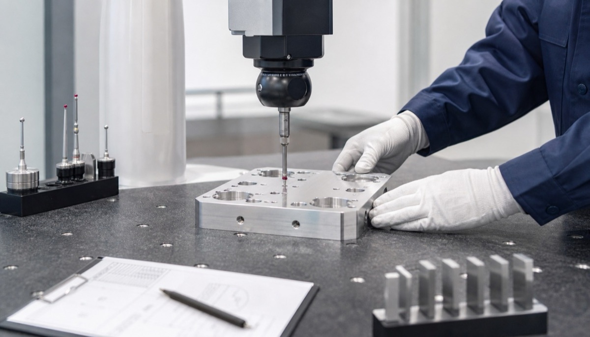
A traceable report should connect measured size, position, flatness and coaxiality to the assembly datum scheme.
Information To Confirm Before Ordering
In one precision robot project, an early DFM review, a shared datum scheme, appropriate 5-axis operations and a CMM feedback loop helped improve yield by about 30 percent. The gain came from controlling the functional chain, not from tightening every dimension.
- Where and under what test conditions is the robot's 0.01 mm repeatability measured?
- Which fits require size, position, coaxiality, perpendicularity, flatness or roughness control?
- What are the actual bearing, reducer and dowel fit classes?
- Will machining, assembly and inspection use the same datum logic?
- Which first-article and batch inspection records must be delivered?
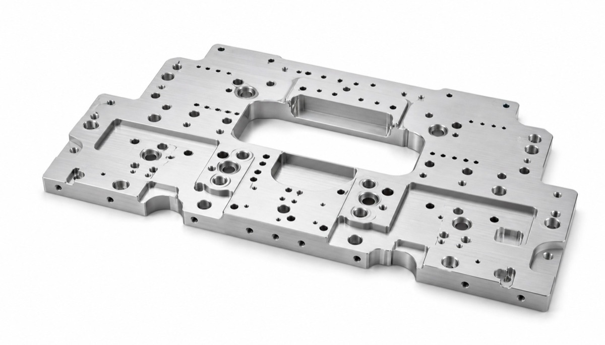
Functional features need graded tolerances; clearance geometry does not need the same accuracy as bearing or dowel locations.
Common Specification Mistakes
A machine list is not proof of capability. Fixtures, cutting strategy, thermal control and inspection records determine whether a tolerance is repeatable. Another mistake is adding the same tight tolerance to every feature, which increases machining and inspection time while hiding the features that truly matter.
Surface treatment, cleaning and packaging must also be planned early. Coating thickness, residual debris or transport damage can change fits after a part has passed machining inspection.
Summary
A robot repeatability target of 0.01 mm should be converted into a functional error budget. Control bearing bores, locating holes, reducer faces and sensor references with suitable processes and traceable inspection, while keeping non-functional dimensions economical.
FAQ
Does 0.01 mm robot repeatability require every hole to be +/-0.005 mm?
No. Only features that directly affect the positioning and assembly chain need the tightest tolerances. Clearance and non-locating features can usually be looser.
What should a machining inspection report emphasize?
It should use the agreed datum system and show traceable results for bearing bores, locating holes, mating faces and the specified geometric tolerances.
Is 5-axis machining always necessary for 0.01 mm robot parts?
No. It is useful when multi-face features or complex geometry would otherwise require repeated setups. Simple parts can meet the requirement with a stable 3-axis or 4-axis route.
How should tolerance grades be selected?
Use the assembly stack, fit function, process capability and measurement uncertainty to assign different tolerance levels to different features.
Ready to get a quote for your CNC machined parts?
Submit your engineering drawings to qiancj@oemach.com. We support prototype sampling and small-batch production with strict tolerance control.