
Define the screw within its equipment interface
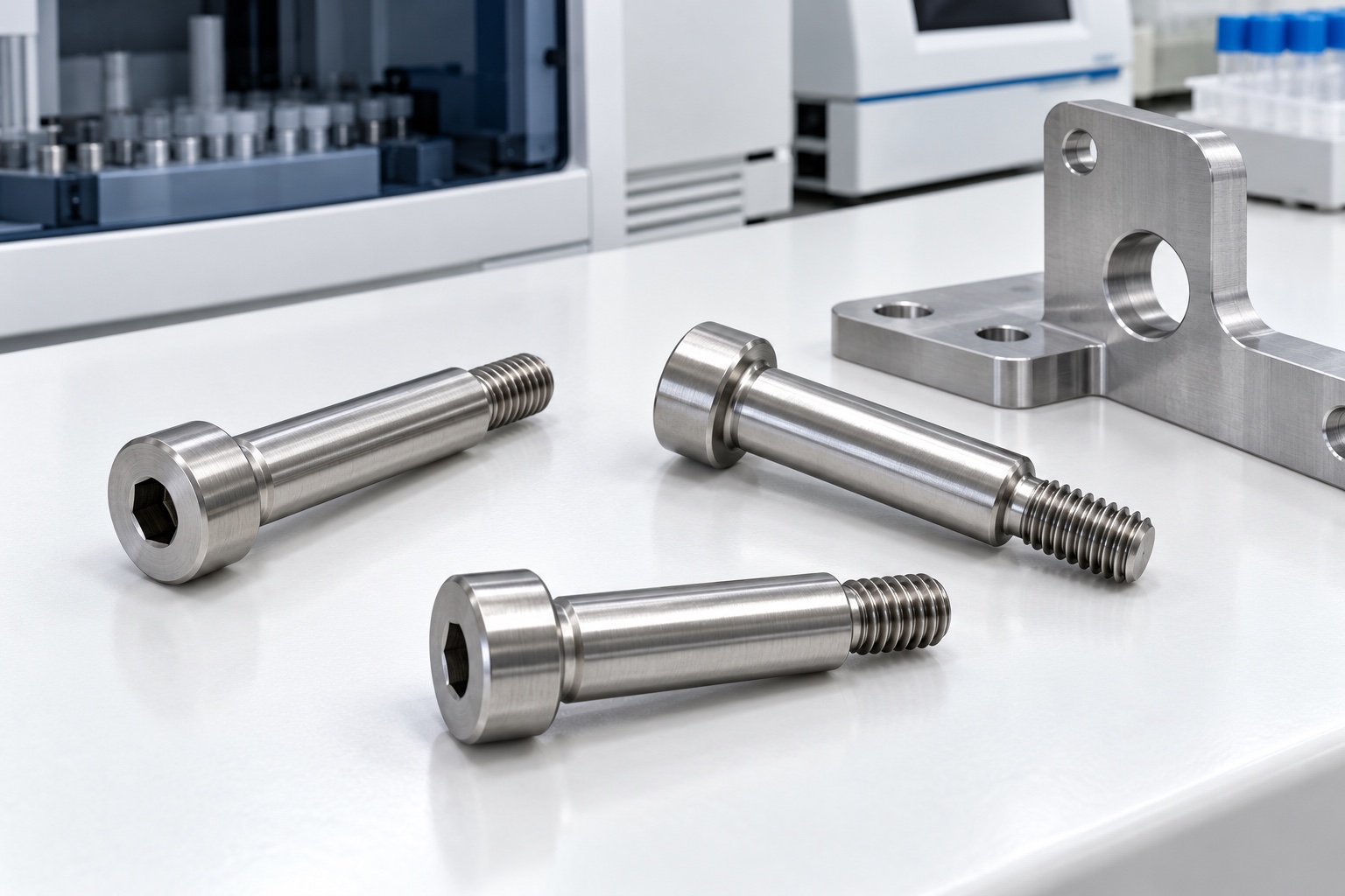
A shoulder screw combines a smooth cylindrical region with a smaller threaded end and a head that provides installation access or contact. Its role in medical equipment depends on the approved mating arrangement, not its familiar appearance. This article concerns a proposed equipment-side custom component, not an implant, surgical fastener or automatically strength-rated standard screw. The responsible designer must specify what the shoulder contacts, how the threaded end is secured and which parts may move. Dimensional acceptance alone cannot establish permissible load, fatigue life, joint retention or the safety of the complete mechanism.

Specify shoulder and thread independently
Identify the smooth shoulder diameter and length separately from thread form, size, pitch, handedness, fit and usable engagement. The cited MISUMI product information treats shoulder dimensions and thread selection as distinct configuration features, providing useful background rather than a qualification for this custom part. A smaller threaded end that fits a tapped hole does not verify the shoulder or installed stack. Do not borrow catalog tolerances, material grades or strength ratings for an unrelated drawing. The actual purchase must state its controlled geometry and acceptance requirements before a supplier plans manufacture.
Resolve the installed axial stack
Relate shoulder length, head contact, mating-part thickness and the intended seated condition in the approved assembly. Identify which components should be clamped and which require a defined freedom of movement. A screw that becomes tight can still have unintended contact or constrain the wrong component. Do not shorten the shoulder, add washers or deepen a mating hole informally until one sample moves. Such changes need design review and revised inspection requirements. This article provides no universal clearance, engagement or tightening value because those requirements depend on the actual joint and equipment function.
Control under-head and thread transitions
A head-to-shoulder transition and the relief near the smaller thread can influence where a mating part actually contacts the screw. Define their approved geometry and relationship to the useful cylindrical region. A nominal shoulder length does not describe every transition or usable contact. Review tool access and the mating part's edge form before production. Do not introduce an undocumented groove simply because it simplifies threading or measurement. A changed transition belongs in the controlled drawing and model, especially when it alters seating or clearances rather than merely changing an exterior cosmetic feature.
Treat material as a specific design input
State the approved grade, condition, stock form and documentation. A proposed 316L screw is not interchangeable with a heat-treated high-strength shoulder screw merely because dimensions appear similar. Do not add a strength-class marking or imply compliance with a catalog standard without actual authorization and evidence. Any required mechanical properties, treatment or testing must be specified for the real component. The design program must evaluate loading and the complete mating-material combination. A material certificate supports identity within its scope; it does not independently establish joint strength, fatigue performance or medical-device qualification.
Plan turning from functional references
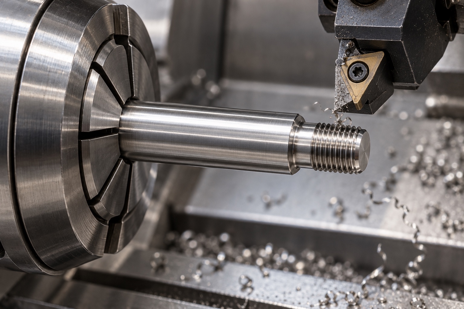
Choose references that relate the smooth shoulder, threaded end, head and intended seating face. Review setup transfers so a convenient chucking surface does not replace the installed functional basis. Workholding must support the part without damaging finished cylindrical contacts. Control chips before later operations and inspection. Tooling and cutting conditions depend on actual material, geometry and equipment, not a universal recipe. Intermediate checks can confirm the sequence but do not replace acceptance of the released screw in the specified final state. A smooth-looking turned surface does not establish every required form or relationship.
Define the head drive and finishing route
An internal hex socket or other approved drive feature needs its own form, depth, edge and access requirements. Manufacturing method and tool access should be reviewed before production rather than inferred from the head's outside diameter. Keep the drive distinct from any temporary manufacturing center feature. A proposed change must remain within approved limits or receive authorization. Do not use an unfamiliar key to force a poorly formed socket into apparent acceptance. The drive, head seating and surrounding assembly access should remain part of the controlled component and installation information supplied with the order.
Inspect edges without altering contact lengths
Examine thread starts and ends, shoulder transitions, head boundaries and the drive opening for attached material or unwanted sharp features. Define acceptable edge conditions without consuming specified contact area or changing usable engagement. Uncontrolled polishing should not hide a damaged shoulder or an unapproved relief. Cleaning and any final surface process must follow the purchased scope with relevant final-condition inspection. A bright stainless appearance does not establish lubrication, friction, corrosion resistance, quantified cleanliness or sterile supply. Keep markings outside functional contacts unless the design explicitly permits their placement and method.
Separate thread inspection from shoulder inspection
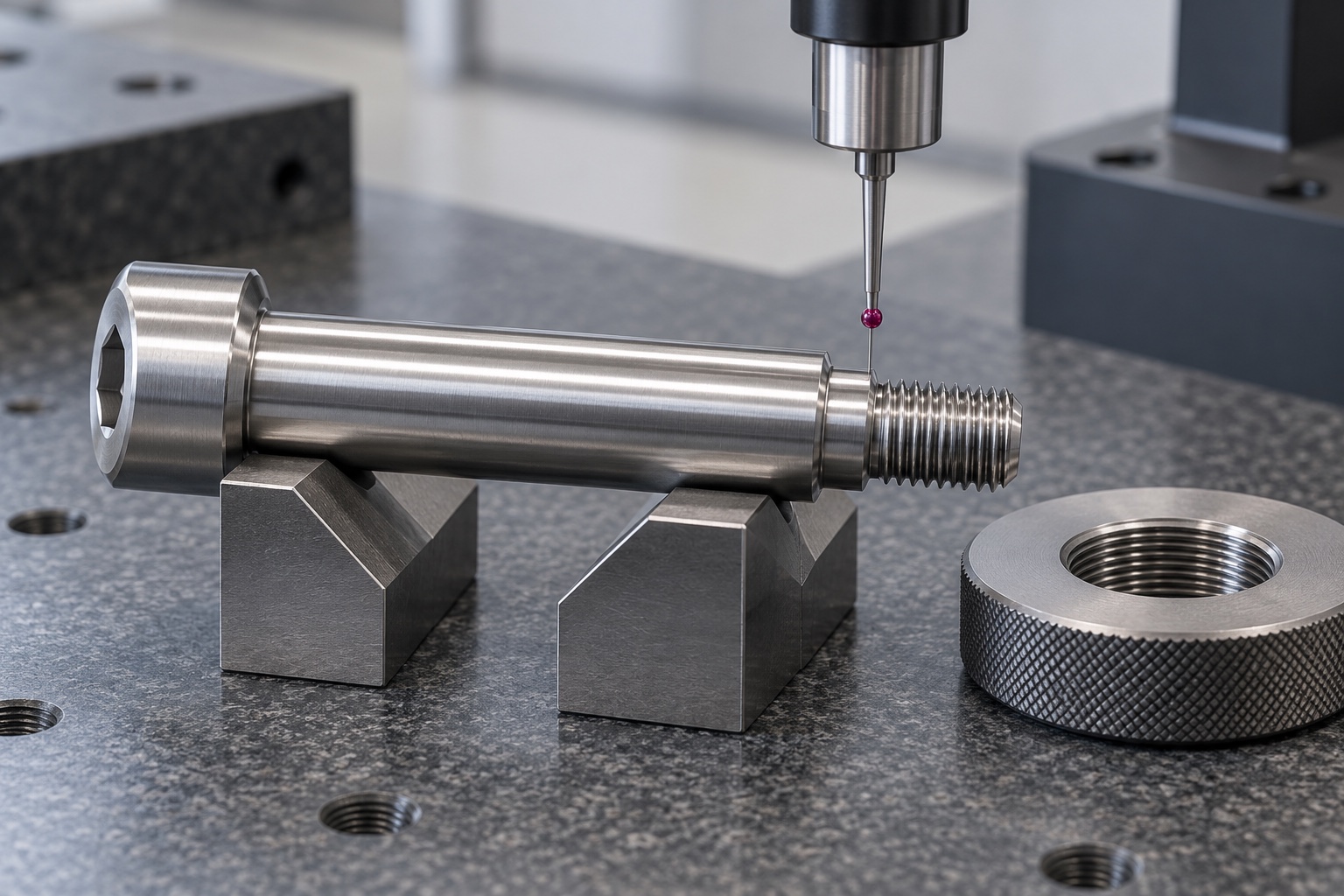
A thread ring gauge addresses its defined thread characteristics; it does not automatically verify smooth-shoulder size, length, form or head relationships. Map every drawing requirement to a suitable method, reference setup and final treatment state. Distinguish surface texture from geometric form where separately specified. An approved mating part may support a limited assembly check, but should not silently replace dimensional evidence. Resolve ambiguous transition measurements before production instead of reporting only thread size and overall length. Preserve the actual material lot and drawing revision with the first-part inspection record.
Bound assembly demonstrations and load claims
An agreed demonstration may check insertion, intended seating, specified movement and installation access with identified approved components. Record revisions, hardware and any authorized surface treatment or lubrication. It does not by itself prove clamp force, resistance to loosening, shear or bending capacity, fatigue life or equipment safety. Those matters require separately approved evaluation of the complete joint. Unexpected binding or contact must be documented before changing the shoulder, mating part or thread. A single hand-operated movement is not a strength test and should not become a general performance claim for the screw.
Protect threads and smooth shoulders in shipment
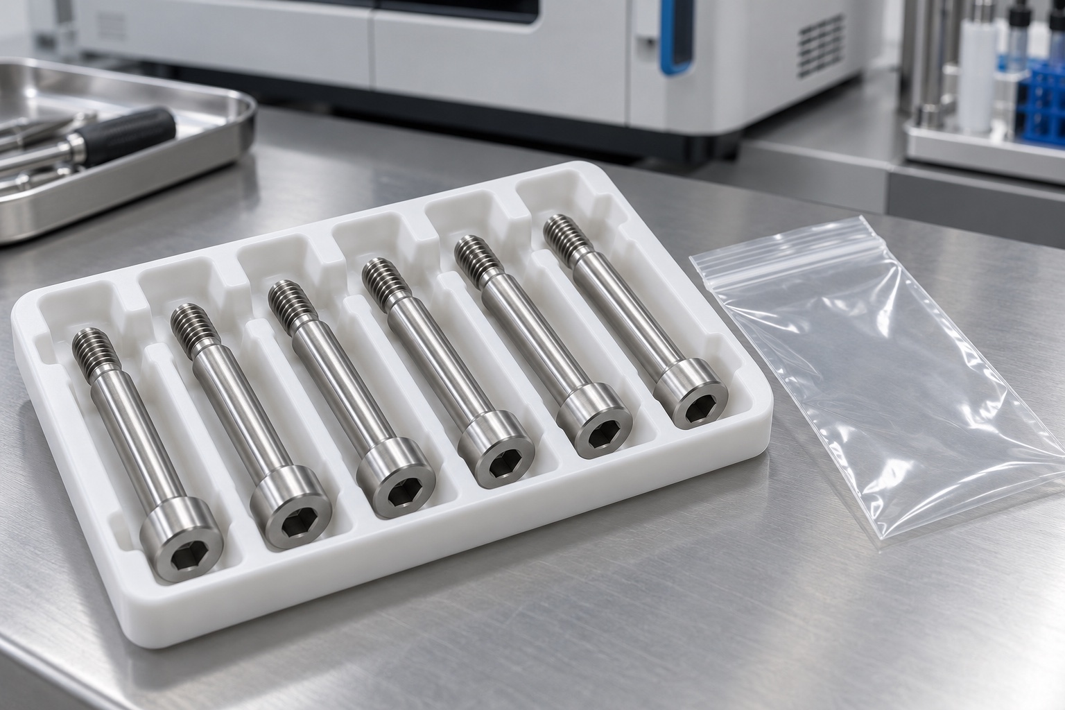
Package screws individually or separate them so threaded tips and head edges cannot damage neighboring cylindrical surfaces. Keep loose hardware away from accepted contacts and avoid unapproved adhesive on the shoulder or threads. Protective materials must suit the agreed cleaning scope without implying sterile delivery. Preserve grade, condition, lot, finish and revision information with the shipment. Identify any trial mating components separately. Receiving personnel should be able to distinguish the approved custom screw from prototypes and similar catalog fasteners with different shoulder lengths, thread forms, materials or documented mechanical-property requirements.
Retain a joint-specific repeat-order baseline
A complete inquiry includes controlled geometry, mating-stack information, shoulder contacts, thread requirements, head drive, material and final process with inspection deliverables. Identify requested fit demonstrations and keep strength or mechanism qualification separate unless explicitly defined. Incorporate approved prototype changes into released documents. Review altered mating thickness, transition geometry, washers, threads, material treatment or lubrication before reusing earlier conclusions. This provides a traceable precision-turned component without claiming that an acceptable thread and attractive shoulder surface alone establish a load-rated or fatigue-qualified joint for medical equipment.
Manufacturer background reference: uk.misumi-ec.com.
FAQ
Does 316L make this a high-strength standard shoulder screw?
No. Grade identity alone does not establish a strength class, standard-product equivalence or joint capacity. The approved specification must define any required properties and evidence, with the actual equipment joint evaluated separately rather than borrowing a catalog rating.
Why separate shoulder length from thread length?
They control different parts of the interface. The shoulder, usable thread, transitions, mating thickness and intended contact must be defined together; a thread that fits does not establish the required axial stack or freedom of movement in the assembly.
Can a relief groove be added for easier machining?
Only within approved geometry or after authorization. A relief can alter transition contact and the useful shoulder region, so it should not be an undocumented manufacturing convenience or a hand-fitted correction to an unexplained assembly problem.
Does a thread ring gauge verify the entire screw?
No. It addresses the characteristics within its defined thread scope. Shoulder size, length, form, head contact and drive features need suitable inspection methods tied to the approved drawing and final condition rather than one successful gauge check.
What can a basic assembly trial demonstrate?
It can show the agreed insertion, seating, movement and access checks with identified parts. It does not establish load capacity, clamping force, resistance to loosening, fatigue life or medical equipment safety without separate approved evaluation of the complete joint.
What changes need review before a repeat order?
Review mating thickness, shoulder and transition geometry, threads, head drive, material, final process and lubrication requirements. Retain authorized revisions so earlier fit or load conclusions are not transferred automatically to a changed equipment joint or a different fastener.

tanghangyun@oemach.com