
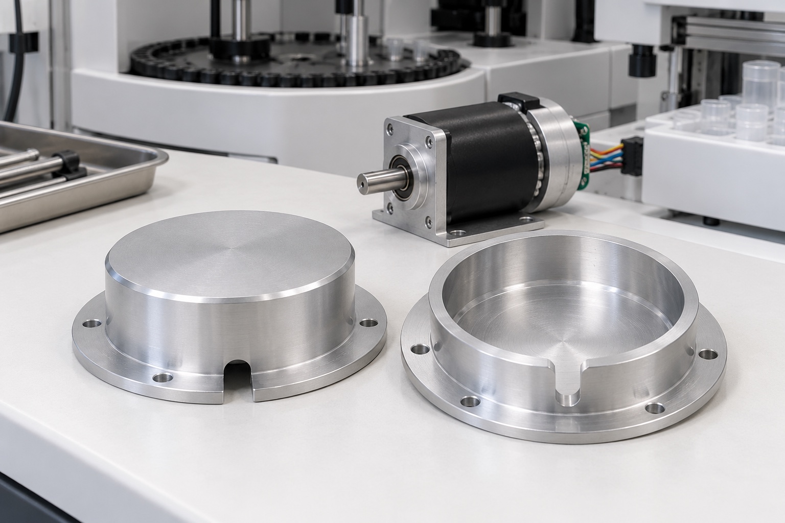
Define the cover's mechanical responsibility
An encoder cover surrounds an identified portion of a medical analyzer's motion-feedback assembly. The equipment designer must define the required enclosure, installed references and surrounding clearances before a supplier can manufacture it. A cup-shaped aluminum part is not automatically an environmental seal, electrical shield or qualified safety guard. This article concerns a proposed equipment-side cover, not a patient-contact accessory or a sterile barrier. Its dimensional acceptance must remain separate from encoder accuracy, contamination protection and complete equipment validation. A photograph of an enclosed motor cannot supply missing design requirements.

Start with the selected encoder's documents
Obtain the exact encoder and motor revisions, mounting instructions, interface drawings and cable information. The cited HEIDENHAIN interface document discusses protection of exposed electronics, providing context for reviewing an actual installation rather than assuming that an arbitrary cap is sufficient. That context does not qualify this custom cover or establish compatibility with a particular encoder. Do not copy another product's protection or shielding claims. The responsible equipment team must identify which requirements belong to the cover and which depend on cable connections, other enclosures or the complete feedback system.
Define the installed cavity envelope
Relate the internal wall and closed end to the approved flange or locating references. Distinguish required clearance from features intended to locate or contact a mating part. An acceptable outside diameter does not establish adequate space around a connector, mounting screw or rotating component. Specify the actual envelope and any relevant operating or installation conditions rather than guessing a universal gap. Review the complete stack before selecting wall thickness. The supplier should not deepen or widen a cavity informally because one loose encoder sample can be placed inside it.
Review cable access without inventing strain relief
An open cable notch needs a defined location, width, depth and edge condition relative to the installed assembly. Identify the approved cable and connector arrangement, including how the cable is routed and restrained elsewhere. A notch through a cover rim is not automatically a cable gland, strain-relief device or sealed passage. Do not introduce an unapproved sharp transition, adhesive or tight interference to retain a cable. Unexpected contact should be documented and reviewed before machining changes. Cable qualification and installation instructions remain responsibilities of the actual equipment design program.
Maintain flange and locating relationships
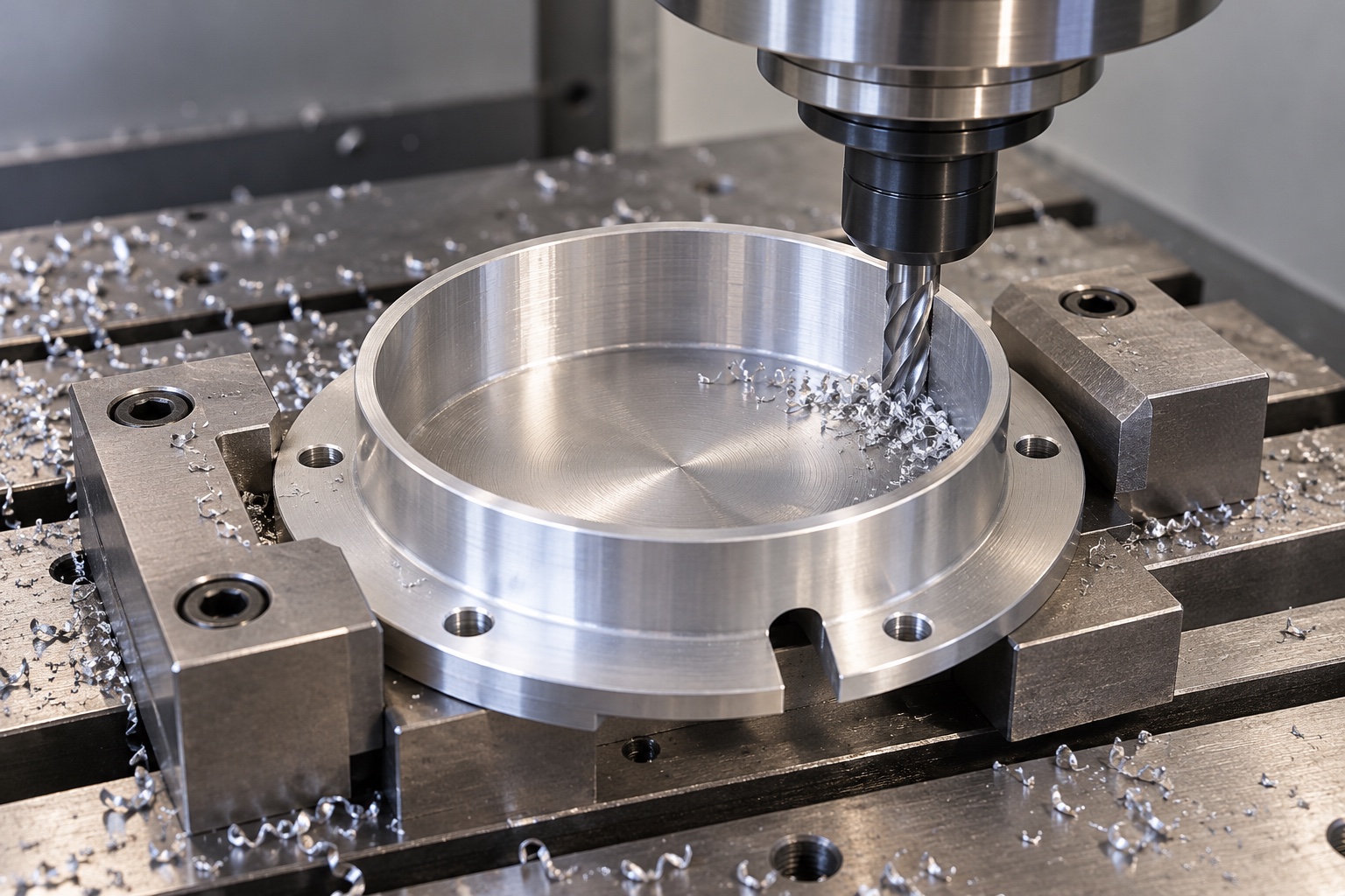
A flange may carry mounting contacts, clearance holes and a separately defined locating feature. Identify those functions explicitly so the machining reference reproduces the installed position rather than a convenient raw edge. Hole size alone does not control the relationship between the cavity and mounting pattern. Review fastener access, remaining material and the approved contact stack together. Extra tightening should not be used to force a distorted cover into place. Any gasket, bonding contact or intermediate component must come from controlled design information instead of an undocumented shop preference.
Plan removal of the internal material
A deep cavity changes the stiffness of its wall and closed end as material is removed. Plan roughing, finishing and setup transfers around that changing support. Keep chips away from fixture contacts and protect the flange during later operations. Turning and milling may both be appropriate depending on the actual features and equipment. There is no universal toolpath, clamp force or cutting condition in this article. Intermediate checks can confirm the route, but final inspection must address the released component in its specified condition rather than a shape held artificially by the fixture.
Resolve corner access before production
The cavity floor transition, notch corners and underside of the flange may limit cutter or inspection access. Review acceptable radii and any necessary relief with the designer before manufacture. A proposed machining convenience should not silently reduce an internal clearance or consume a mounting contact. Preserve authorized changes in the drawing and model. Distinguish remaining material from unwanted burrs so finishing does not become uncontrolled redesign. A sample that fits over the outside of an encoder is not evidence that every hidden feature can be manufactured, cleaned and inspected repeatably.
Inspect hidden edges and final surface state
Examine notch boundaries, mounting-hole exits, the cavity entrance and internal transitions for attached material or unwanted sharp features. Define suitable edge requirements without changing approved clearance or locating geometry. Cleaning must follow the purchased scope and must not conceal damaged contacts. If coating or another treatment is specified, agree masking, documentation and final-condition checks. Bare silver illustrations show a geometry concept only. A smooth exterior does not establish shielding continuity, optical cleanliness, sterile supply or a quantified particle level inside a medical analyzer motion assembly.
Create an accessible dimensional inspection plan
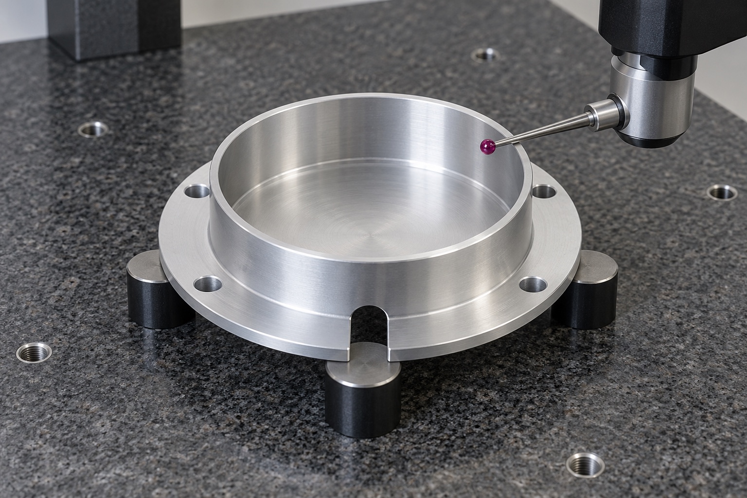
Map each drawing characteristic to a suitable method using identified flange and locating references. Address cavity diameter or profile, depth, closed-end condition, notch position and mounting-pattern relationships as required. An outside size report alone is incomplete when the accepted interface depends on internal geometry. Record support and final treatment state. Resolve inaccessible measurements before production instead of substituting easier unrelated dimensions. An approved mating assembly may support a separately defined fit trial, but its identity and limitations must be recorded alongside rather than silently replacing the required component measurements.
Separate fit trials from protection testing
A documented fit trial may check seating, fastener access, cable clearance and the agreed internal envelope with identified components. Record encoder, motor, cable and cover revisions with installation conditions. The trial does not by itself demonstrate ingress protection, electrical shielding, encoder accuracy, thermal behavior or equipment safety. Those matters need their own approved evaluations for the actual assembled configuration. Do not transfer observations to another connector or cable route merely because the cover still bolts to the same flange. Unexpected interference should be resolved before accepting production geometry.
Protect cavities and flange faces in transit
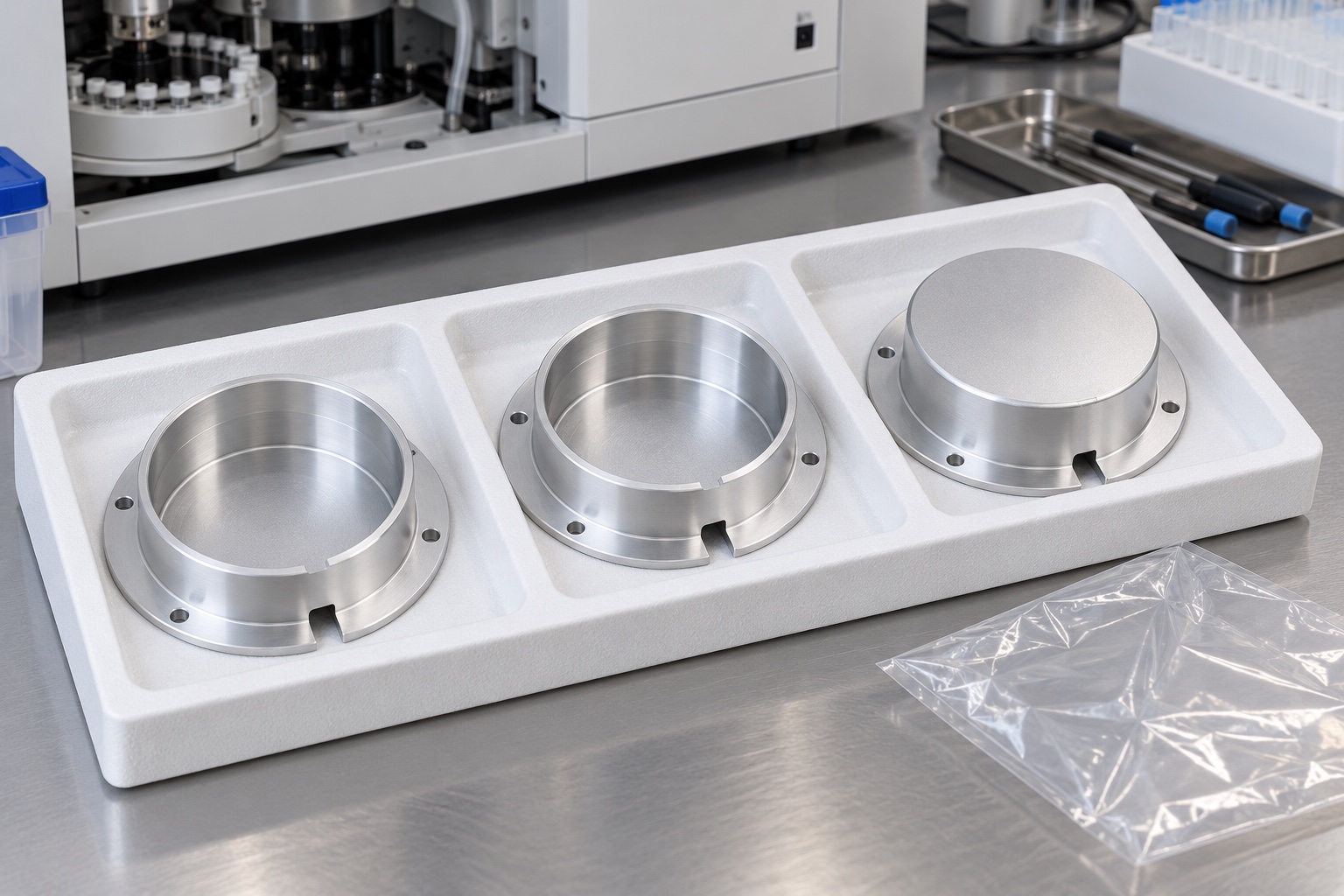
Packaging should prevent neighboring covers, hardware and protective materials from rubbing the flange, notch or internal wall. Support the component without squeezing thin regions. Keep unapproved adhesive and loose fibers out of the cavity within the agreed cleaning scope. Ordinary transport bags are not sterile barriers or evidence of a tested environmental seal. Preserve material, finish and revision identity with the shipment. Receiving personnel should be able to distinguish accepted production covers from prototypes or variants intended for different encoder envelopes and cable arrangements before installing them.
Preserve the entire installation baseline
A useful inquiry includes the controlled model and drawing, approved encoder and motor documents, cable arrangement, mounting stack, material condition, final treatment and inspection deliverables. Identify fit demonstrations and keep protection or feedback-system qualification separate unless explicitly included. Incorporate authorized prototype changes into revised documents. Review changed connectors, cables, locating features, coatings or neighboring components before reusing previous conclusions. This makes the cover a traceable mechanical interface without asking a CNC supplier to invent encoder requirements or claim that an attractive aluminum cap validates the medical analyzer's motion-feedback performance.
Manufacturer background reference: www.heidenhain.com.
FAQ
Does an accepted cover prove environmental protection?
No. Component inspection verifies agreed geometry. Environmental protection depends on the complete enclosure, cable passages, interfaces and installation, and requires separately defined evaluation. An open notch should not be described as a tested sealed passage merely because the cover fits.
Why inspect the internal cavity rather than only outside size?
The installed encoder, connectors and cable arrangement can depend on internal clearance and its relationship to mounting references. Define those requirements and accessible inspection methods instead of assuming that an acceptable exterior proves the hidden envelope.
Is a cable notch a strain-relief device?
Not by itself. It is a defined mechanical opening. Routing, restraint, connector requirements and any protection function must be specified for the actual cable and equipment assembly rather than invented from the shape of a cover rim.
Can cavity geometry be adjusted to a sample encoder?
Only within authorized drawing and process limits. Any design change needs review, controlled revisions and corresponding inspection requirements; an unidentified sample should not become an undocumented production standard or imply compatibility with another encoder version.
Do the silver images define the final coating?
No. They show representative geometry. The actual order must specify any approved treatment, masking and final inspection, with electrical or environmental requirements evaluated separately rather than inferred from surface color or appearance.
What changes need review before repeat manufacture?
Review the cover, encoder, motor, connector, cable route, mounting references and final treatment. Preserve authorized revisions and avoid transferring earlier fit, protection or feedback-system conclusions automatically to a changed installation in medical equipment.

tanghangyun@oemach.com